In the post 1.5.2. Blender 4.5 & ACES 2.0 I created an image to show the render result with the new ACES 2.0 view transform.
In this article, I want to examine the same Blender scene with different view transforms and working color spaces. What interests me is that shader values change their meaning depending on the used working color space. But at least in Blender, this is not at all clear or even communicated to the user.
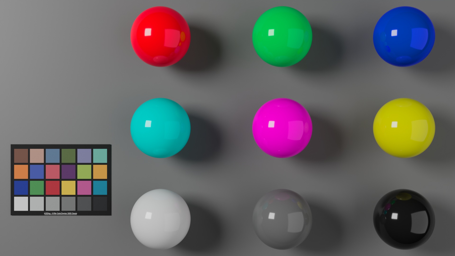
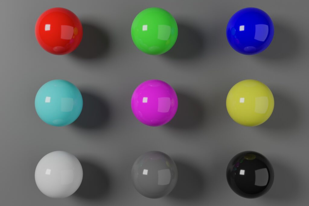
Default OCIO – No ACES – just “Standard”

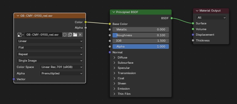
This is a sRGB tagged JPG file. The “Display Device” was set to sRGB by default. Blender states in their OCIO config that the working colorspace or “Internal scene linear space” for this rendering was:
- scene_linear: Linear Rec.709
- rendering: Linear Rec.709
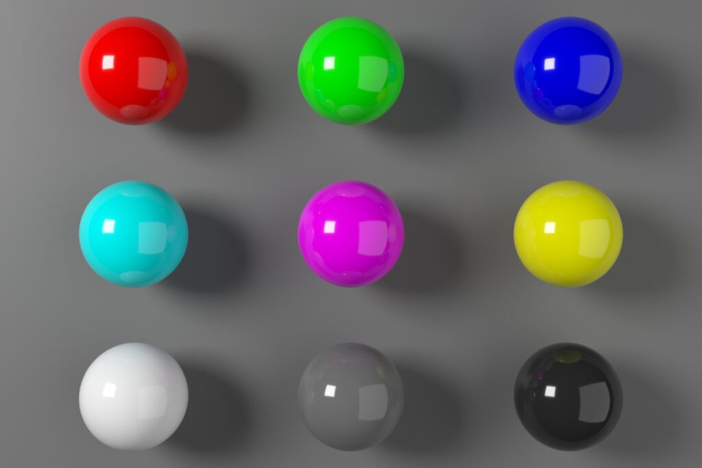
The arrangement of the spheres or balls reminds me of a simple color checker. The colors of the spheres are set to pure red, green, blue, cyan, magenta, and yellow, followed by a white, a middle grey, and a near-black sphere.
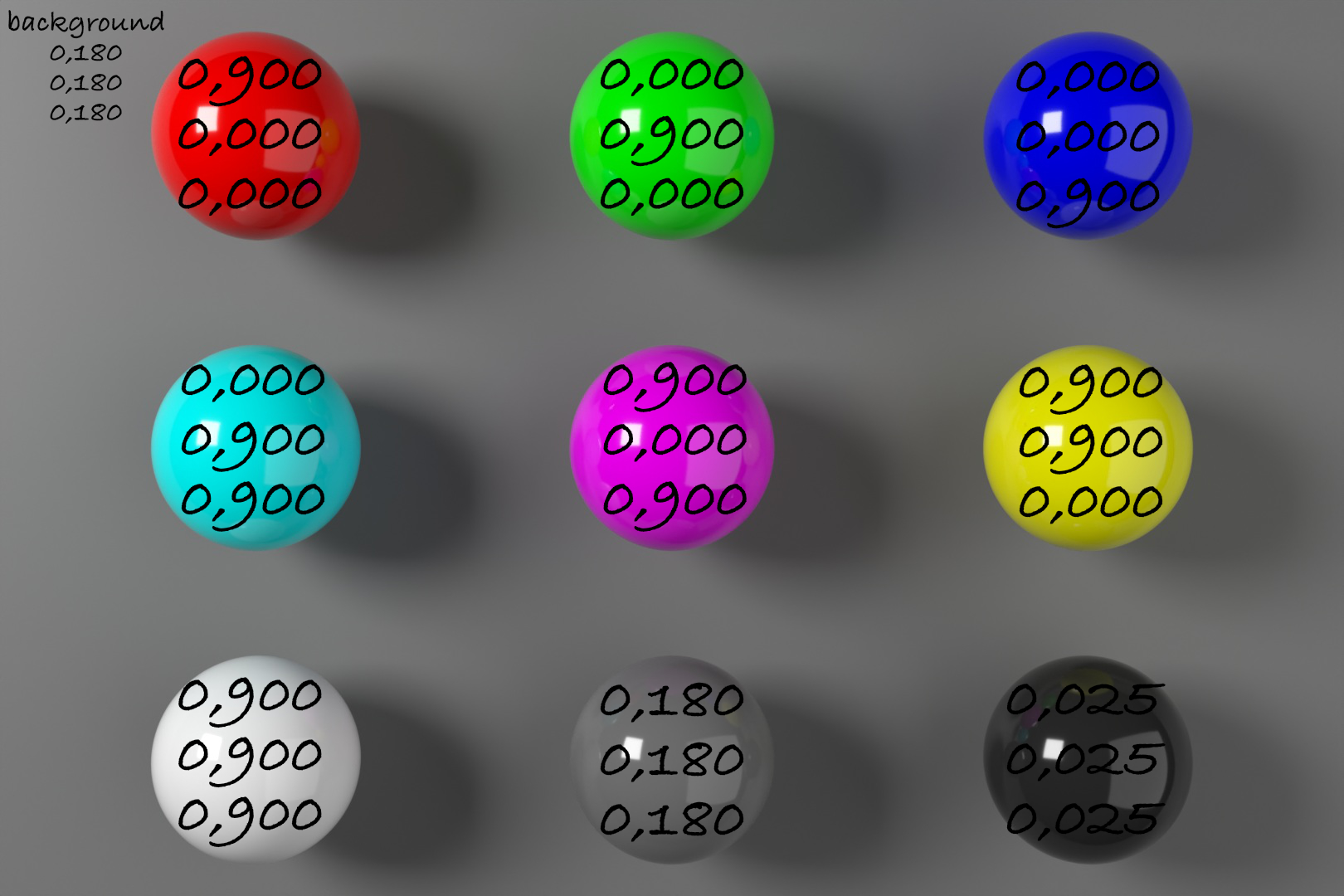
Another way to look at the blender scene is by only thinking in ratios.
Two area lights with varying distances and sizes emit R=G=B light with the same intensity of 1.0 and are the only sources to light the scene. Each of the six colored balls has a principled shader with a “base color” of 0.900 in one or two of the three RGB channels. The remaining three spheres and the background have shader values of 0.900, 0.180, or 0.025 in all three RGB channels.
In a simplified way each object reflects 2.5%, 18%, or 90% of the emitted RGB light in varying RGB channel variations.
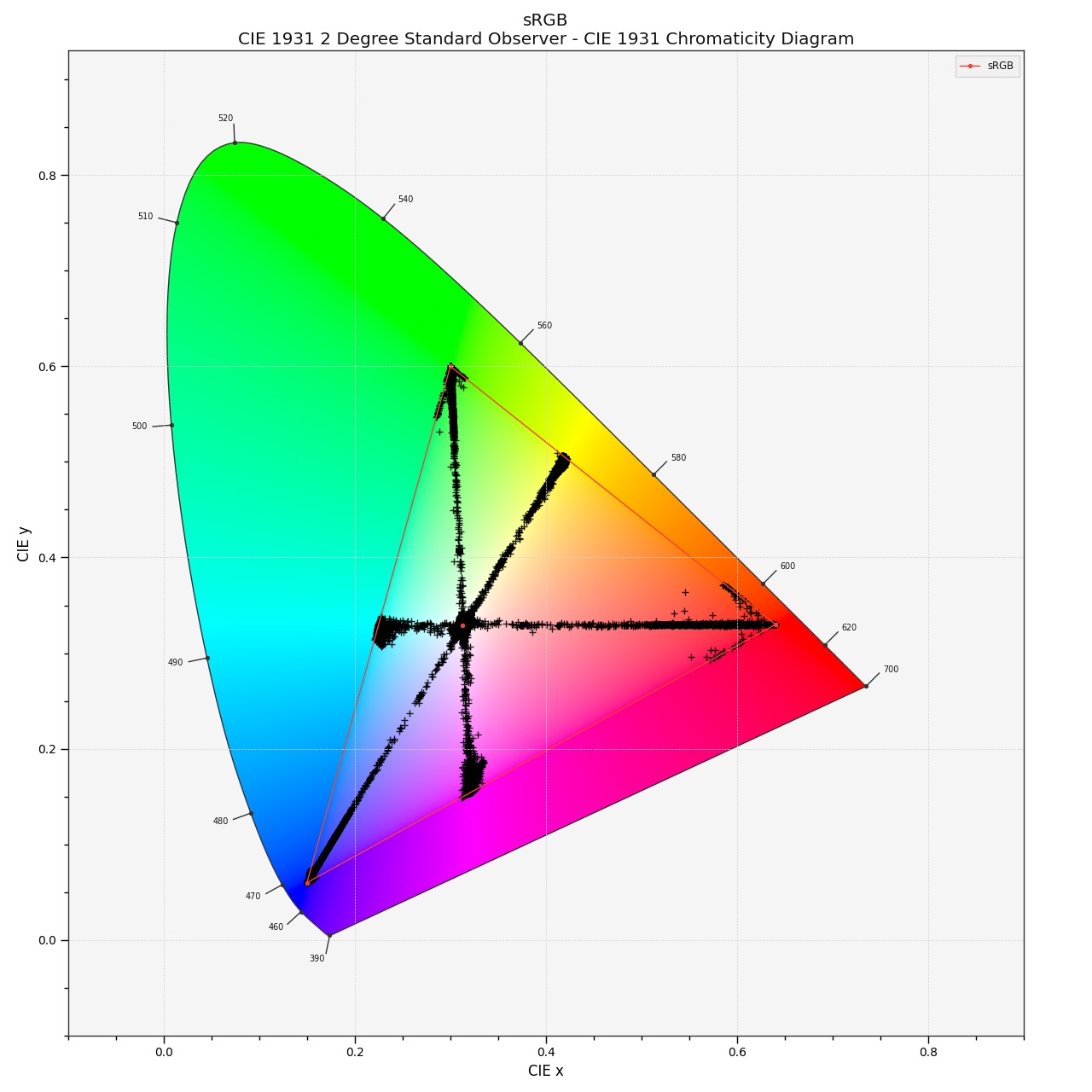
A plot of the EXR file with the help of “COLOUR” shows that all the RGB values lie inside of the sRGB/Rec.709 gamut and therefore should be able to be displayed with every sRGB display.
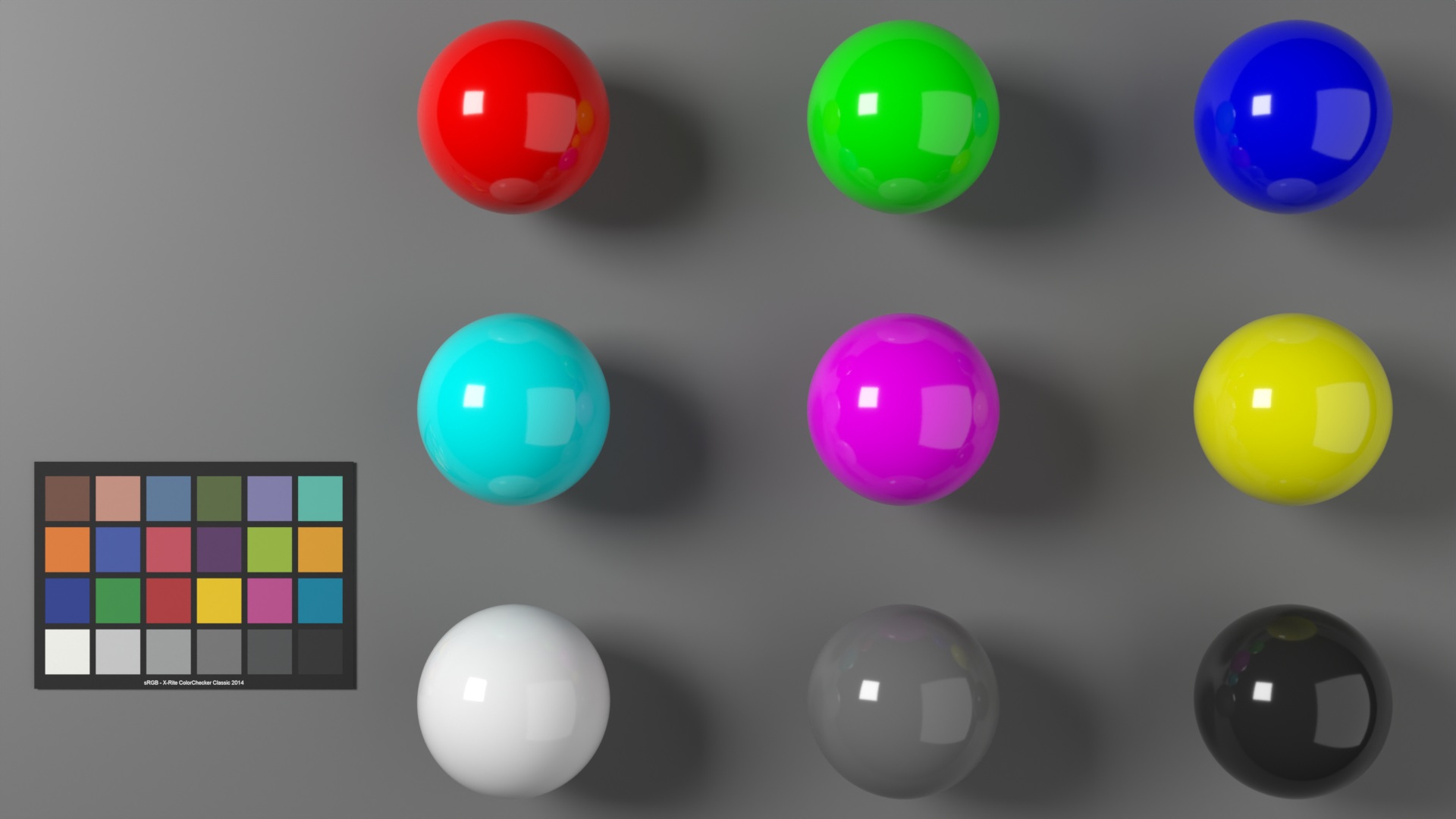
Switching to ACES 2.0
The moment Blender starts with a different OCIO config, the working color space and the view transforms can change.
The OCIO config “cg-config-v3.0.0_aces-v2.0_ocio-v2.4.ocio” seems to refer to the working color space here:
- scene_linear: ACEScg
What I find interesting: If a DCC application changes the default OCIO config with a new version of the DCC or the OCIO environment variable is pointing to another OCIO config, the user might not even be aware that a change happened at all.
Blender does not warn the user for example when a different OCIO config is active while loading a .blend file that was created with the default OCIO config. So I set the OCIO environment variable to the new ACES 2.0 config, loaded the last .blend file, and saved it under a new name.

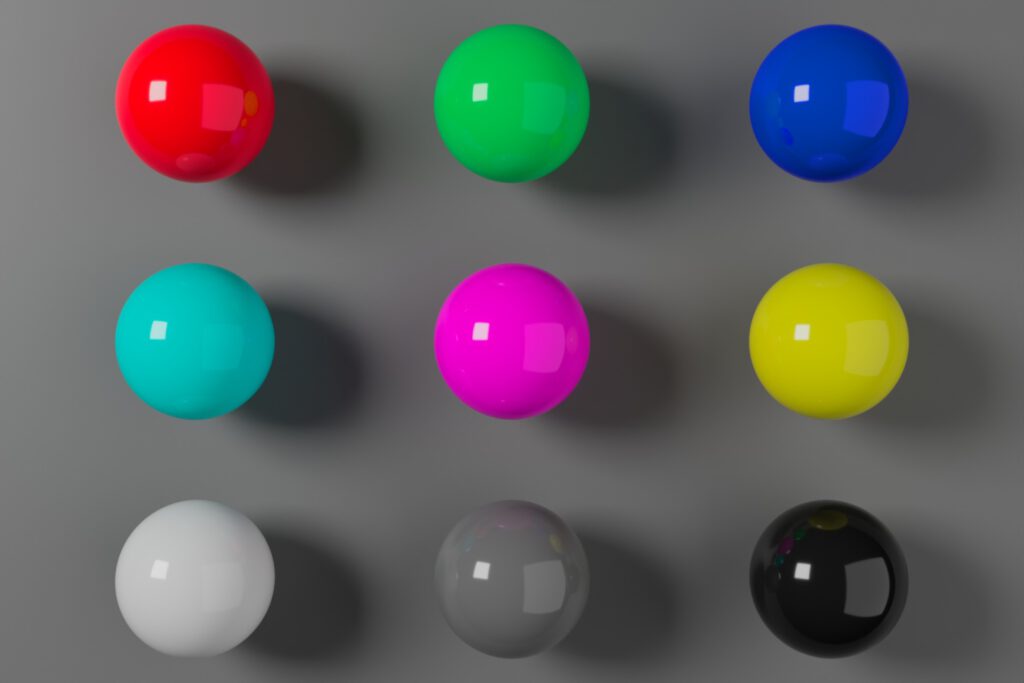
At first glance, the new rendering does not look “that” different from the one before. However, for me, especially the red and magenta spheres are “screaming” too many saturated colors in my eyes. The other colored spheres seem a bit dull in comparison. A side-by-side comparison should help to spot the differences better.
On the left is the non-ACES image, and on the right is the ACES 2.0 image.
Now the changes between the two images are certainly more obvious. The red ball seems to glow, the green looks a bit cyan and duller, the blue ball is less blue and has a dark reflection where the magenta sphere reflects into it, and so on…
What changed?
The .blend file did not change. The light intensity of the area lights (1.0) did not change and the shader values of the objects (mostly 0.900) in the scene did not change.
The rendered EXR image data did not change!
Only the presented image result is different.
What changed is the view transform and the scene exposure raise of 2/3 of a stop in the right JPG image. I altered the scene exposure to get a similar overall exposure feeling for both of the images. To make them more look alike.
Also, the working colorspace changed from linear-sRGB to ACEScg. But I just stated that the EXR image data is identical. Yes, the image data is identical, but how I view or interpret the image data changed.
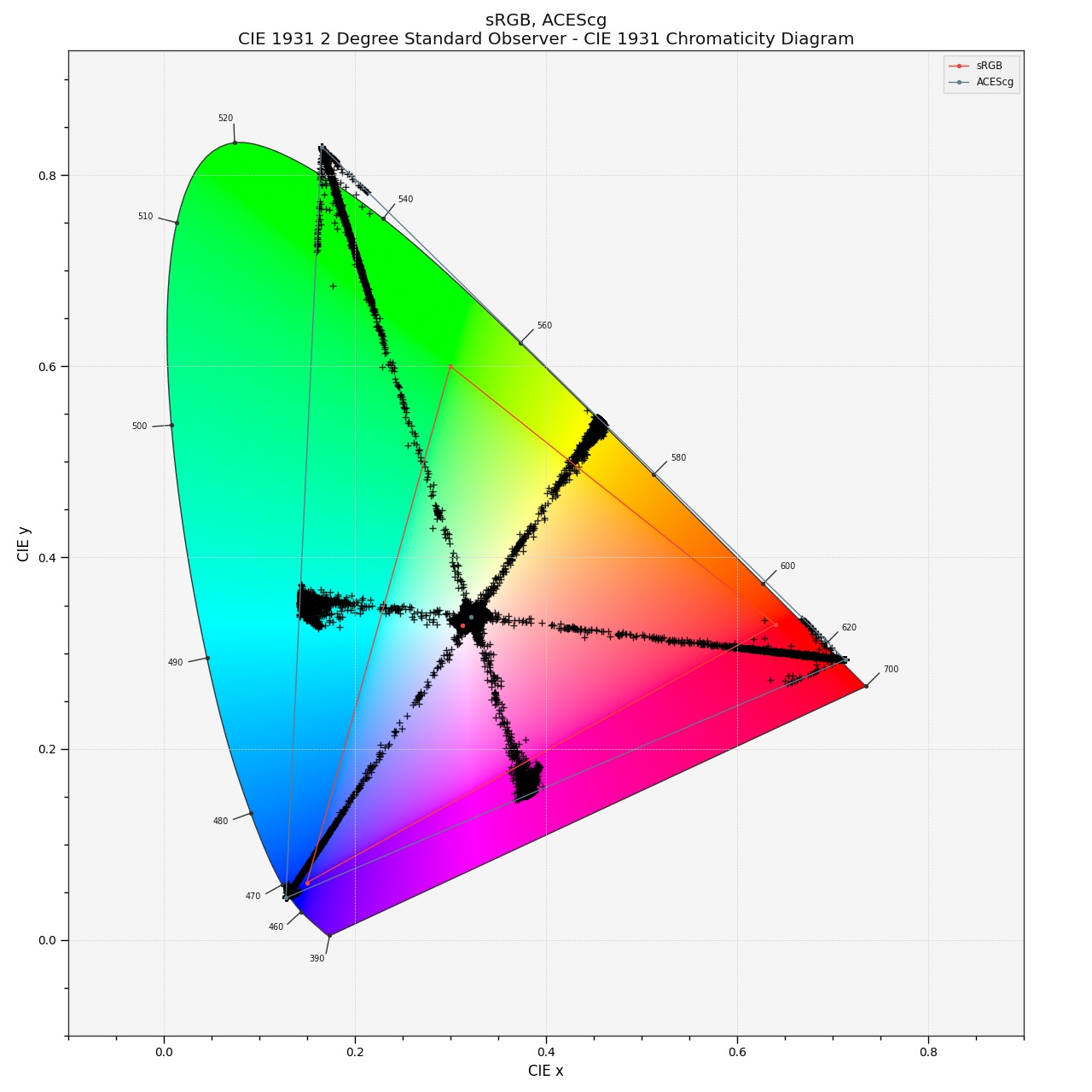
A plot with colour-science shows this clearly. All the plot points accumulate at the positions of the ACEScg primaries, far away from the sRGB primaries position. This plotted data is shown in the working color space, not what ends up on your display!
Most of the colored spheres now have laser-like properties. If there would be a display to see this image I assume it would look rather painful to the eye.
In 2017-2019 I was lucky to watch some prototype laser projector screenings at the IBC convention in Amsterdam. One demonstration showed a snippet from Pixar’s Inside Out. The colors seemed flickering in my eyes similar to watching a laser show.
So no wonder that ACES 2.0 has a problem displaying these “pure” laser-like color values on an average sRGB display. The next plot shows “what” actually comes out of your display.

This is the plot of the actual image data that gets sent to the display. The newly introduced gamut compression algorithms of ACES 2.0 have to work hard to squeeze all the values in the displayable range of an sRGB display.
A comparison of both plots shows the differences even better. One observation when looking at the plots makes me think on the left the colors are more evenly spread from the maximum saturation to the achromatic center white point. But on the right more plot points are crammed around the primaries but getting less dense on the “way” to the white point.
Left sRGB / Right ACES 2.0 sRGB
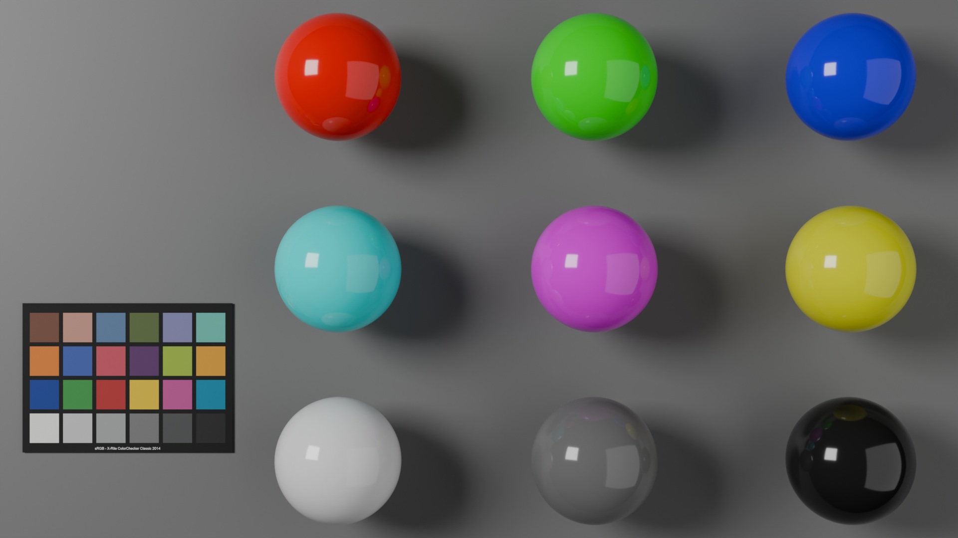
ACES 2.0 with adapted shader values
To avoid the laser-like object colors, one way could be to convert the shader values from the initial .blend file from linear-sRGB to ACEScg values.
Sadly Blender 4.5 lacks a “Convert Colorspace” node in the shader tree, although it is present in the compositing environment. A workaround is to use EXR image textures with the values 0.900 in R, G, or B and set the IDT or source color space to “Linear Rec.709 (sRGB).
After repeating this step for all six colored spheres the rendered result looks like this – followed by the plot of the image result.


To compare the three rendered images so far, here comes sRGB / ACES 2.0 (adapted shader values / ACES 2.0 (no adapted shader values) in a row.
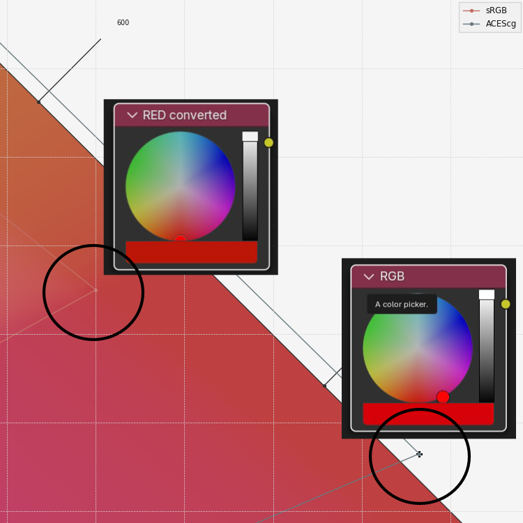
An idea for a Blender color-picker
I think it would be great if the Blender color-picker could somehow tell the user: with this OCIO config, using this working colorspace, your selected color values are far outside the gamut of sRGB and at the boundary of the ACEScg gamut. The UI should be a lot more elegant than this mockup that I made to illustrate the idea 🙂
Be aware of the working color space!
There are many OCIO config options now available that can be tried out with Blender and other DCCs. I listed some of the newer ones in this blog post.
It’s important to check what the proposed working colorspace in each OCIO config is to avoid unwanted image results. The working colorspace could be the one labeled “scene_linear”, “rendering” or “reference space”, but it doesn’t have to be.
Blender is not the only DCC that might add confusion to the user when switching to a different OCIO config. The same is true of most other DCCs in one way or another I am afraid.
I find it helpful to think in ratios of RGB rather than simply saying I just created a “super-wide-gamut” rendering that looks amazing or awful.
A good long read is this thread on ACESCentral.com which covers similar topics.
A slider setting of 0.900 in the red channel can be used to display an sRGB-red, a different P3-red, or again a different single wavelength Rec.2020-red…”color”.
To our eyes, each red will look different only by assigning it a different meaning as long as your operating system “knows” how to handle the various outputs.