Looking into the deep reds
Changing the working colourspace in a graphics application is rather easy, but there are some implications that I was not aware of. In the following article I will have a deeper look into an issue that mostly surfaces when using very pure RGB colours in different working color spaces.
There are many ways to interpret rendered EXR image data. I am reusing the Blender scene that was created for the article “3.5. One Scene – many images“.
The setup
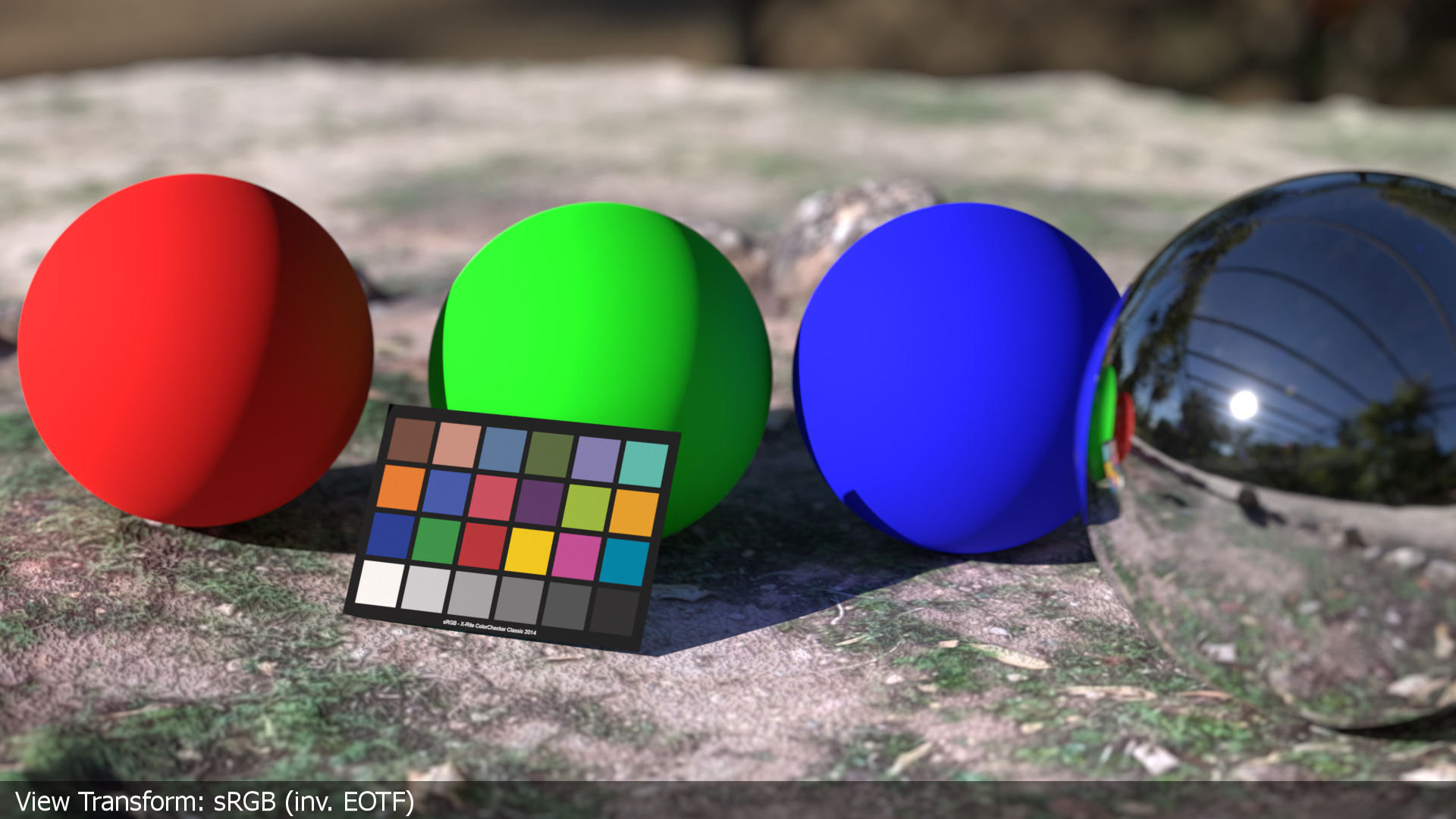
- A Blender scene in the default linear-sRGB working color space.
- The View Transform is set to “Standard” for a sRGB display (inv. EOTF)
- The spheres have a principled shader with base color R, G and B values of 0.800 or 80% diffuse reflection of the incoming light.
- The chrome sphere is only there to see a bit more of the HDRI.
- A simple test scan of a ground scenery that comes with a simple diffuse texture that I captured with “Scaniverse” on an iPadPro.
- The HDRI is actually shot at the same spot where the ground texture was scanned. The HDRI is balanced to the sRGB color checker and saved in the color space linear-sRGB.
So far so good. You may or may not like the result of the rendering, the “clipped” areas on the sunny side of the three spheres and the fact that every value above 1.0 in the scene gets clipped by the inv. EOTF. Without any tone-mapping to bring higher values in a displayable range between 0-1 there is no way to avoid clipping.

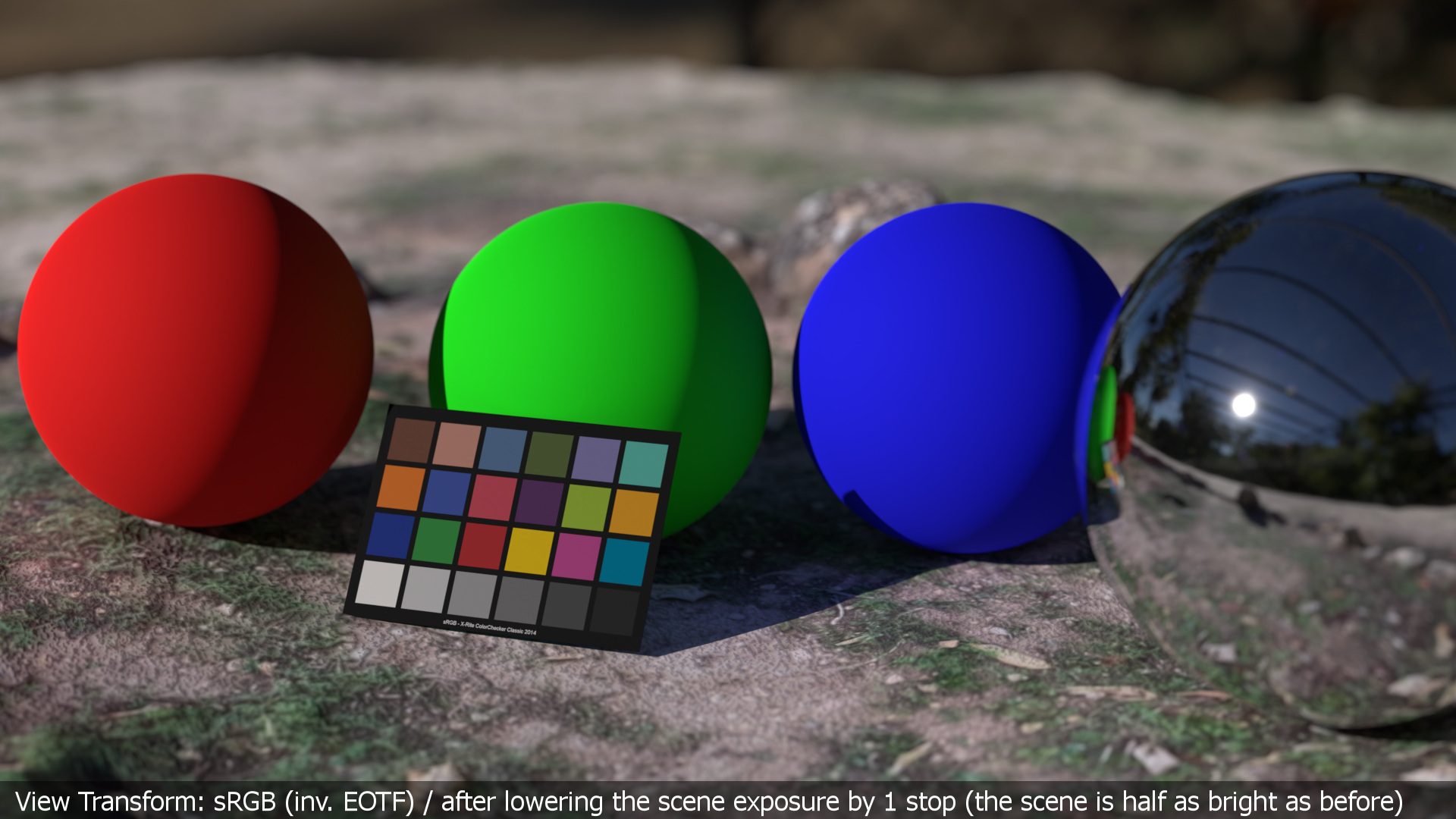
One way to bring down more values into the range between 0-1:
For this default sRGB display the range of values are too high so I could just lower the scene exposure by -1 stop to bring nearly all the values of the coloured spheres back into a displayable range. But the image gets overall darker.
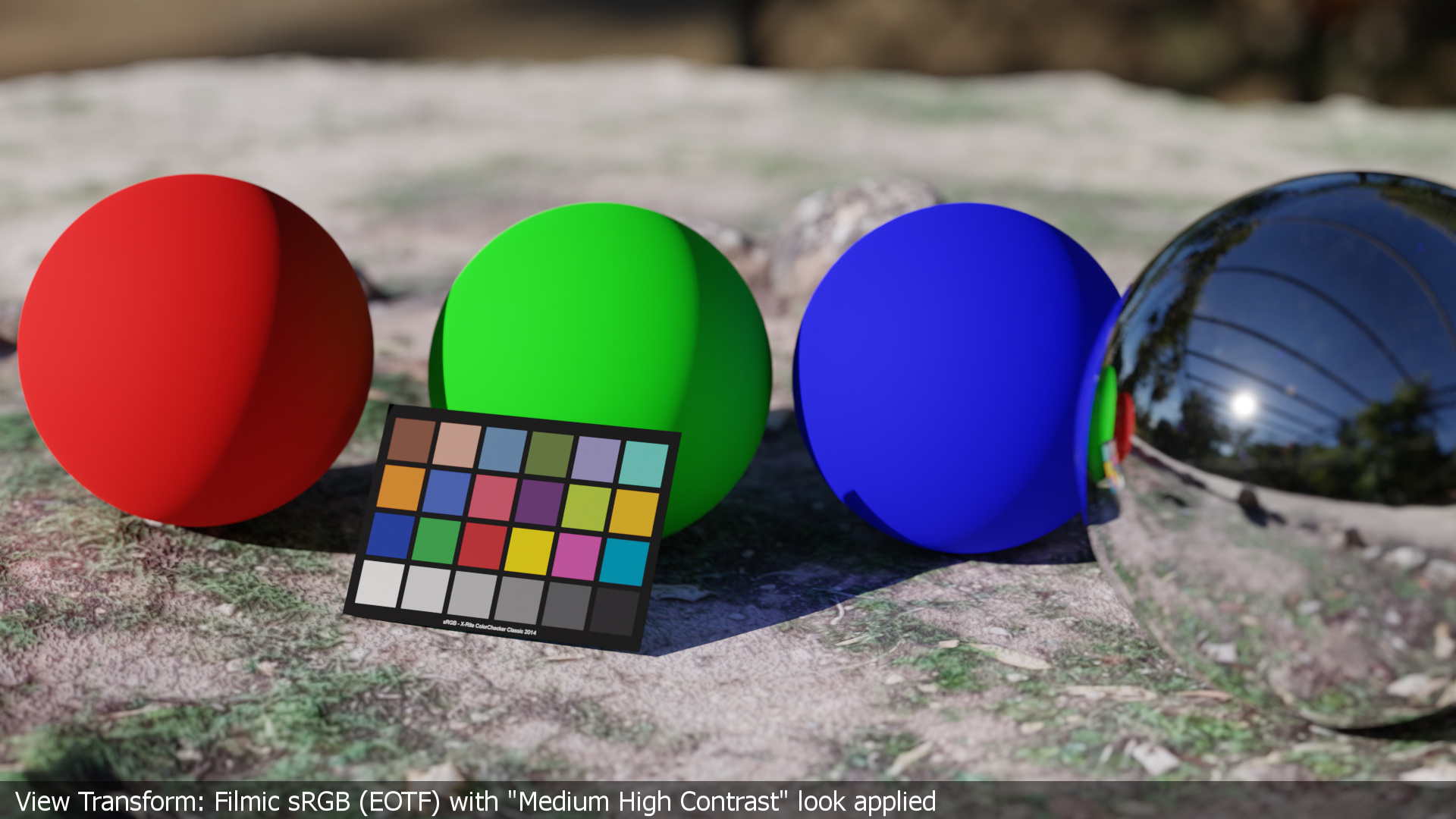
Another way to solve the clipped values is to use a different view transform. Luckily Blender comes already with a set of different view transforms combined with looks that help to avoid the harsch clipping. After piping the image data through the “Medium High Contrast” look, only the center of the sun will be clipped at the display, but this is of course more than fine. The image looks brighter and more sunny again.
working and display colourspace are the same
Up to this point I am more or less in control of what I will see at the end of the processing chain on a display. The working colourspace primaries in the Blender scene are related to the display primaries of sRGB/Rec.709. The inverse EOTF is baked into the JPG images that are presented here on this website. The display hardware is applying the Electro Optical Transfer Function to the received image data and the resulting values drive the display’s emissions.
There are many more view transforms (or also called Display rendering transforms) available to the user: ACES, OpenDRT, Truelight, Filmic and the new AgX, Davinci Resolve RCM2 and many more from the different digital camera vendors like ARRI, RED, Sony, Canon, BlackMagic Design, … Some of these view transforms I compared in the article “3.5. One Scene – many images“.
imagine SWITCHING to aces without knowing why
Maybe you never worked in a different working color space and been asked to render your Blender scene in ACES and render out a JPG in Blender or Nuke. I looked into the new Blender feature in the article “Blender 3.2 and render colorspace overrides“.
A wrong render result could end up like this:
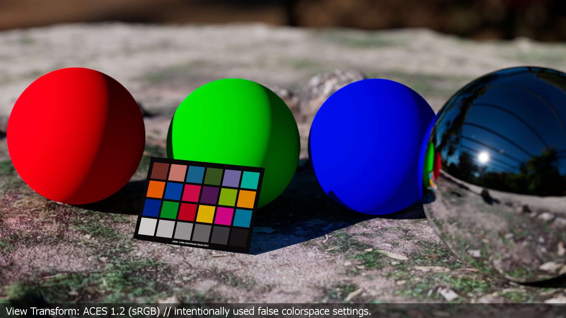
What happened?
- The HDRI is not converted from lin-sRGB to the working color space ACEScg.
- The ground texture actually uses the right IDT “sRGB-Texture” and is converted to the working color space ACEScg.
- The shaders of the three spheres still reflect 80% (0.800) of the incoming light, but now from the “perspective” of the working color space ACEScg instead of linear-sRGB.
- The color checker texture is also not converted properly and shows too strong and weird colours.
These are only the obvious settings in the Blender scene file that are not right when you want to render in ACES. But there is much more going on under the hood. While I was writing this article I got a friendly reminder of how many unwanted changes are happening in the resulting images.
Here is a for sure incomplete list of stuff that happens when switching from a linear-sRGB working space to ACES and make use of the ACES system:
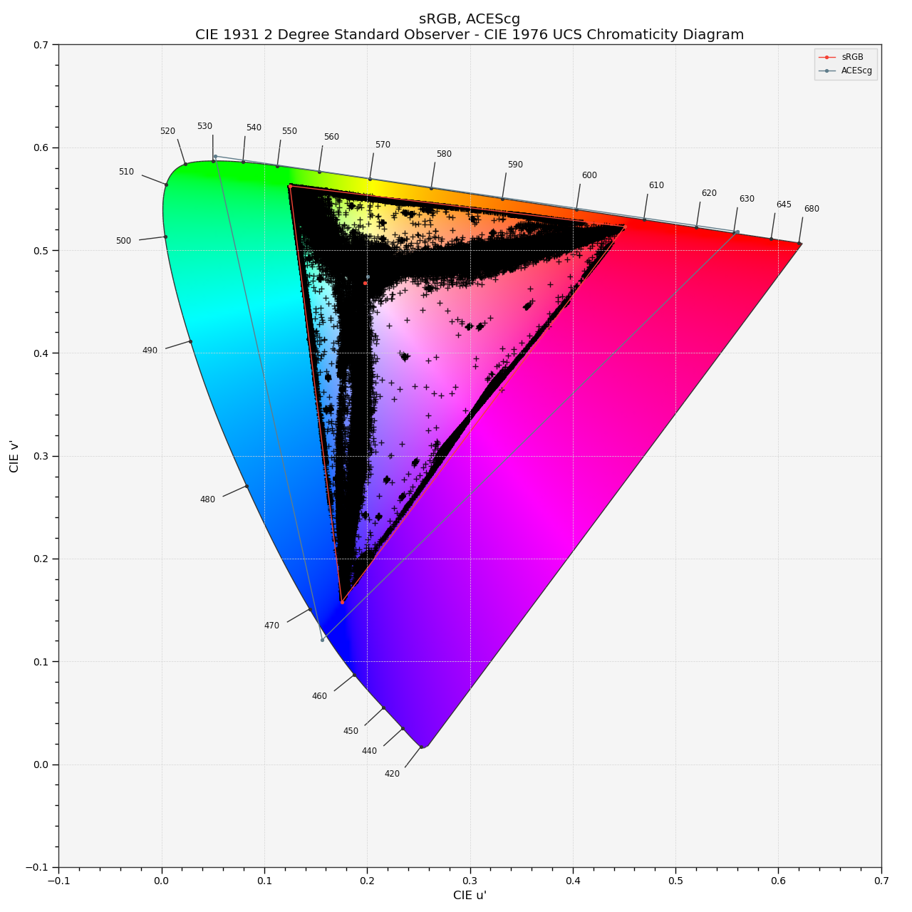
- The working colourspace is now ACEScg. The primaries of this colourspace are even further out than even a Rec.2020 (pure laser primaries) display could show. ACEScg uses virtual primaries. There’s already a lot to think about what that means when using pure ACEScg primaries in a shader for example.
- The ACES RRT (Reference Rendering Transform) renders for a virtual “display”. The ACES ODT (Output Device Transform) “forms” an image that actually can be displayed.
- On the way from the working colourspace to the display are happing some wanted and some unwanted changes to the image data:
- Color matrix operations that convert from one colourspace to another colourspace
- Gamut clipping at the display
- And some additional bits and pieces that I am not even aware of.
- Please check out the very informative and deep diving article from Chris Brejon about OCIO, DISPLAY TRANSFORMS AND MISCONCEPTIONS.
using ACes properly but facing a new issue
So from here on I am using the ACES system and will observe some changes in the following images that I am presenting here. I want to focus on the working colourspace ACEScg and the color matrix operations that I marked in bold above.
I am writing this article from an ACES user perspective. At least the moment I am not able to fully describe what it means to “convert” ACEScg RGB values into display linear RGB values that can be used to drive a display.
Anyways, first let’s get the Nuke side in order. Nuke 13 is set to ACES 1.2, the working color space is ACEScg. The rendered file from Blender needs the right IDT in the read node, which is linear-sRGB, as this is my working color space in Blender with the default settings.
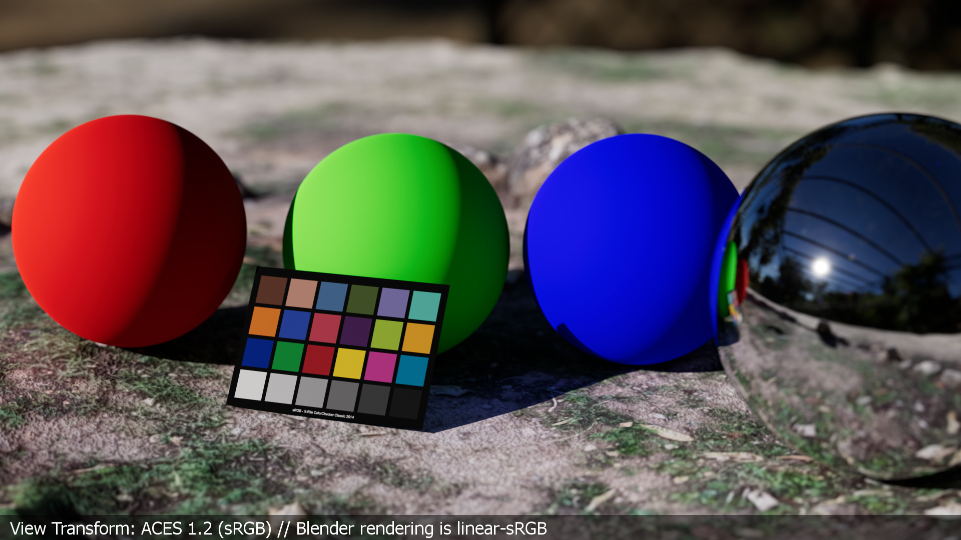
The coloured spheres look a bit better, the color checker looks right and the sky reflection in the chrome sphere looks good too. The ACES RRT & (sRGB) ODT renders the image that is shown here as a JPG output.
The DRT or display rendering transform of ACES 1.2 introduces some visible unwanted changes as well. The red sphere gets a slight orange tint on the sunny side. The green sphere gets a greenish-yellow tint on the sunny side. The blue sphere looks too saturated and lacks shading in the shadow areas. It should be added that the shader settings are not very “natural” and pushing the system to the limit. Still a robust display rendering transform must handle this kind of situation.
Now that the Nuke side is “fixed”, I headed back into Blender but this time with the OCIO config set to ACES 1.2. (You could also try out the new OCIOv2 configs that are available now). In the Blender/ACES scene I changed some settings and shader values:
- The HDRI was converted from lin-sRGB to ACEScg before importing it as an “image texture”.
- The ground texture uses the right IDT: sRGB-Texture.
- The color checker texture is also changed to use the right color space.
- The shaders of the three spheres are converted from linear_sRGB to ACEScg.
I rendered the ACEScg EXR file and compared it to the linear-sRGB EXR file using the same ACES RRT&ODT for sRGB.
Overall both renderings look very similar now. You can identify each render with the text under the color checker. But there is a difference if you look closer.


Can you spot it? Without an A/B comparison it is not so easy to see the differences between the two images. The video below shows the difference a lot better.
Especially the shadow area of the red sphere and a bit less on the green sphere is different in both renderings. The shadow areas which are hit by indirect lighting are brighter in the ACEScg render than in the linear sRGB render.
So what is the difference between the two renderings? The base color shader values of the three RGB spheres have a different meaning depending on the working colourspace it seems.
the rendering from the lin-srgb scene
In the linear-sRGB working color space, the red sphere’s base color value of 0.8 / 0.0 / 0.0 in the principled shader reflects 80% of the incoming “RGB lights” from the HDRI. But only in the red channel, as green and blue is at “zero”.
The finished rendering gets ingested into Nuke with the read node setting IDT linear-sRGB. A color matrix transforms the lin-sRGB values into the working colourspace ACEScg. On the way out to the display, the sRGB ACES RRT & ODT applies the inverse matrix again to convert from the working color space ACEScg to the display color space sRGB .
Again, it is important to note that the display rendering step is very crucial to the image results. A different “View Transform” will end up with a different interpretation of the image data.
the rendering from the acescg scene
In the Blender scene with working color space set to ACEScg (different OCIO config), I entered converted base color shader values for the red, green and blue sphere. The red sphere’s values are:
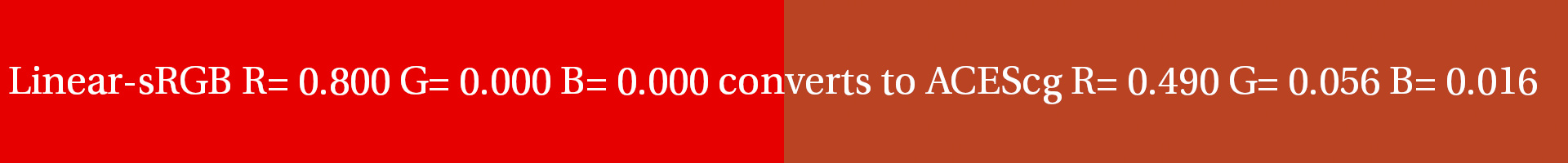
That means in the Blender/ACES scene the red sphere reflects around 50% of red, around 5% of green and around 1% of blue of the incoming “RGB lights” from the HDRI. The result is that more light bounces can end up with a stronger indirect diffuse reflection on the shadow side of the spheres.
I must say after working with ACES for several years now I was not aware of this effect. In renderings with more “natural” colours that are not that extreme and pure in R, G or B, the difference might not be that noticeable.
But this effect that happens in the indirect diffuse reflections sparked my interest even more. So I created another even more simple Blender scene to really push the visibility of the differences when working in two different working color spaces.
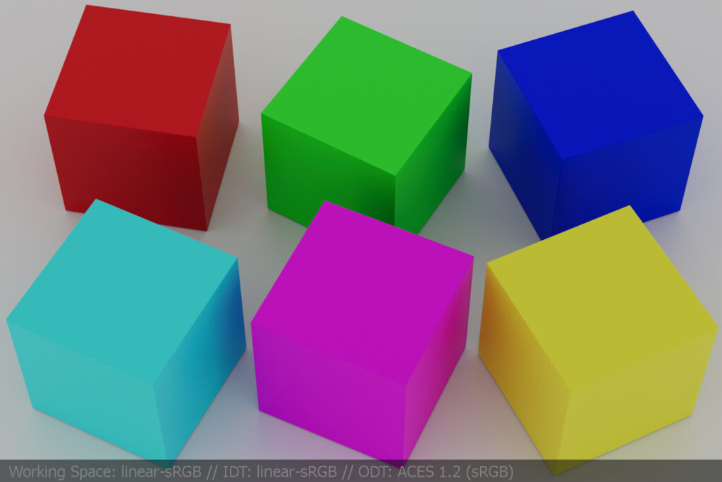
so From now on everything is 0.800 or 80%
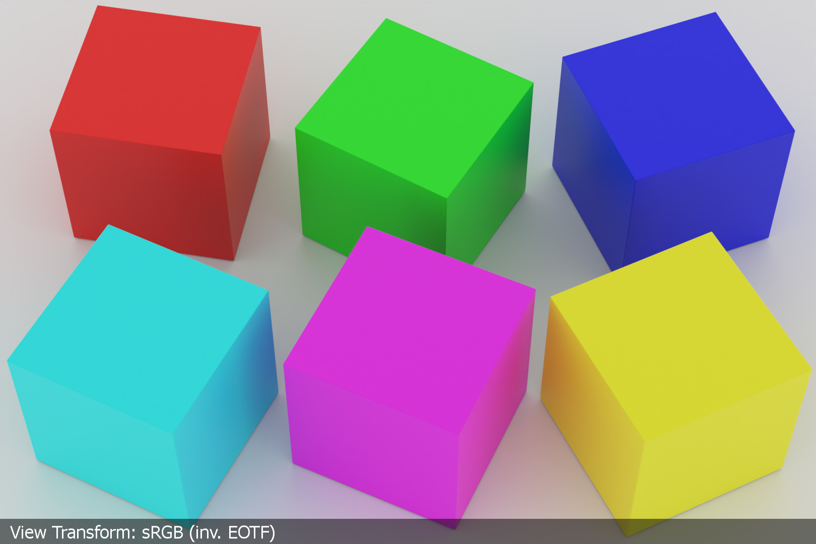
The spheres were turned into cubes, but six of them in the six possible maximum emissions that can end up on a display. Red, green, blue, cyan, magenta and yellow. Each cube has only a principled shader with a base color value of 0.800 on or two of the three RGB base color shader values. The ground plane has an achromatic base color value of 0.800 in RGB and the world shader is lighting the scene with an achromatic value of 0.800 in RGB as well. This is a very simple and graphic image. Simplifying the scene helps me to understand what will happen now in the next steps.
The next image comes from the same rendering, but viewed through the ACES 1.2 (sRGB) RRT&ODT.

working colourspace linear s-RGB vs. ACES-cg

Above are the same two images again, but each in comparison between the working color space linear-sRGB and ACEScg. Up is the linear sRGB rendering viewed through the ACES pipeline and below is the ACEScg rendering with converted shader values so that they look and appear the same in the resulting JPG images.
Again, the differences in both renderings are not very easy to spot. Therefore I made another A/B comparison video clip to show the differences better.
That is a kind of odd result, isn’t it? By changing the working colourspace from linear-sRGB to ACEScg and trying to have matching colours for each cube on output, I am ending up having higher indirect diffuse reflections.
turning on the red lights
To really flesh out the differences when switching to the working color space ACEScg, here comes another rendering where I only changed the world shader. It emits now 0.800 only from the red component. This is an even more unreal lighting situation, I don’t think you could light a “scene” in this way in the “real” world and capture an image with a digital camera of that scene.
The point of this extreme unrealistic lighting setup is to see now what happens to the six cubes.

Each cube that has a value of 0.000 in the red component of the shader appear near black in the image.
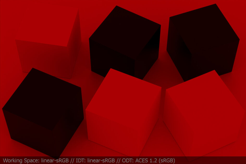
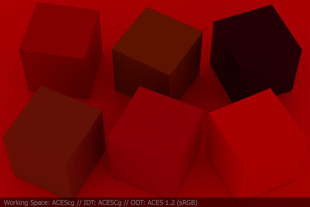
That is a big difference in the A/B comparison above.
conclusions
So what does that mean? First of all it means when you converting colorspaces you change the red, green and blue component ratios. This will happen in a 3D environment and also when dealing with digital camera footage.
How can I fix the issue in 3D? Instead of converting the shader values from the linear sRGB Blender scene to ACEScg, I could simply say in the Blender/ACES scene the red sphere gets a shader value of 0.5/0.0/0.0. This would eliminate the increased indirect diffuse reflections.
Maybe with a shader base color value I can do that, but with a texture this would not work. I need to convert a texture to ACEScg with the help of the IDT sRGB-Texture to make the texture appear with the “right” colors.
The whole issue will happen in other colour workflows too. So it is a problem? I am not sure, but for sure it was an interesting experiment for me to do.
Left lin-sRGB (inv. EOTF ST-2084) – right ACES ODT (HDR)