Working in-between the layers
This is the second part of the Photoshop & ACES series. This time I will go through another matte painting example, but in more detail and using some conversion 3D-LUTs inside of Photoshop. In the first part of this two part series, I went through a basic setup for the Photoshop & ACES work(around)flow.
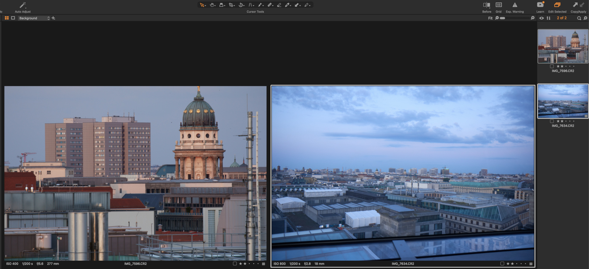
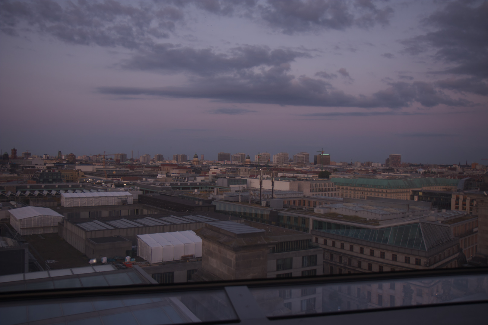
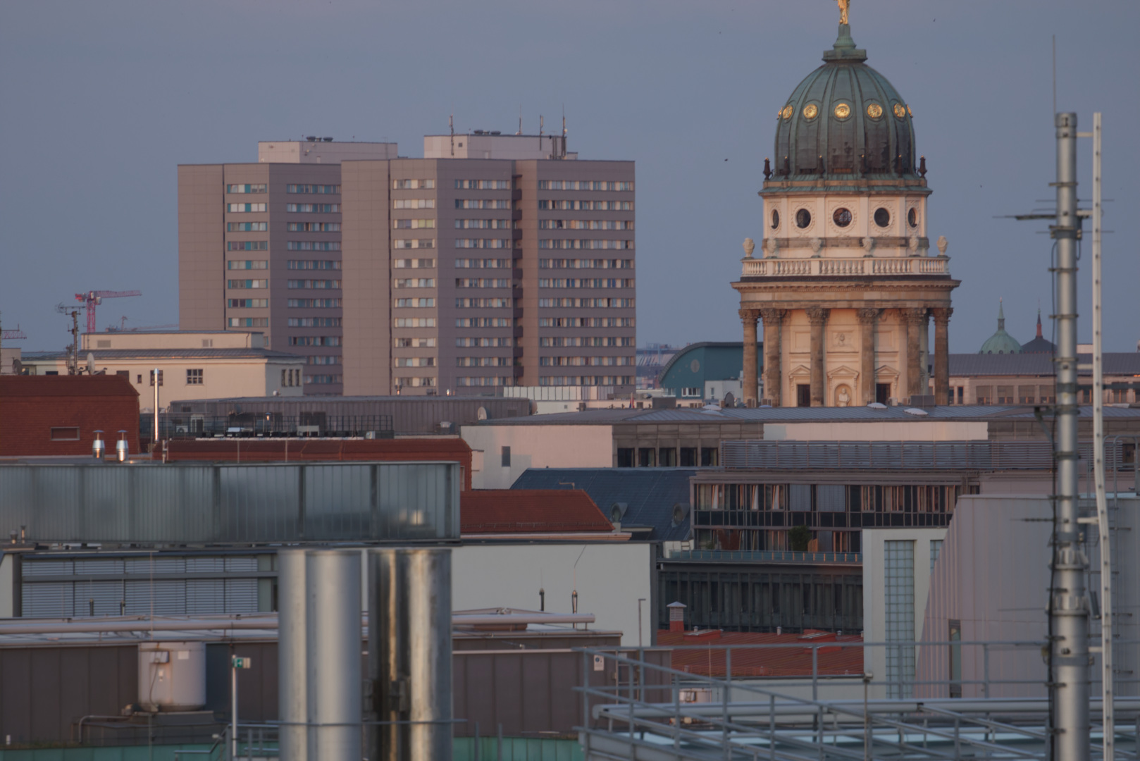
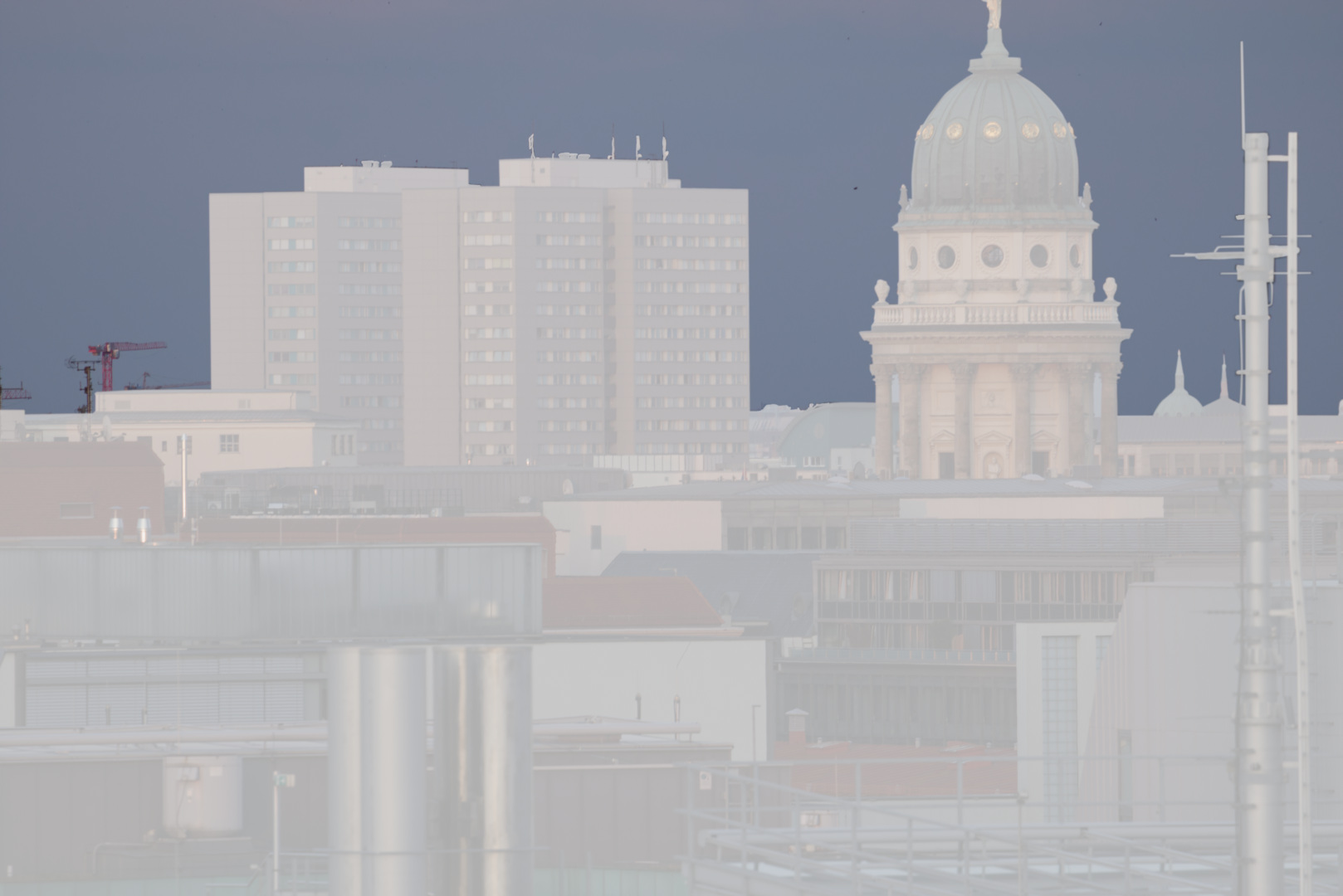
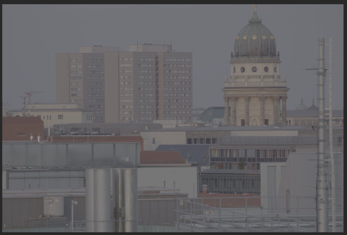
This is the footage I want to work with: three Canon 7DMKII raw images. The first two I will treat as my “camera” plates.
I converted them with Affinity Photo to ACEScg EXR files.
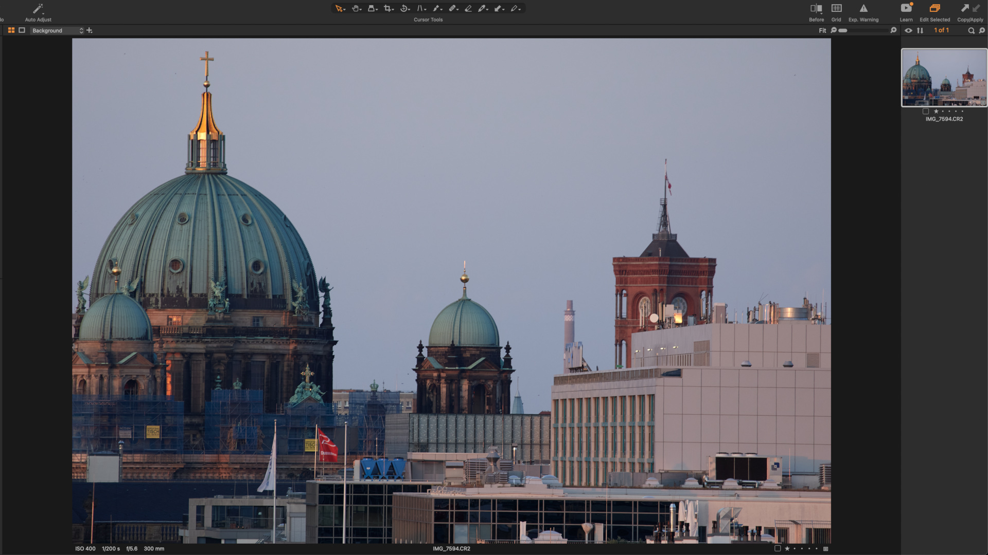
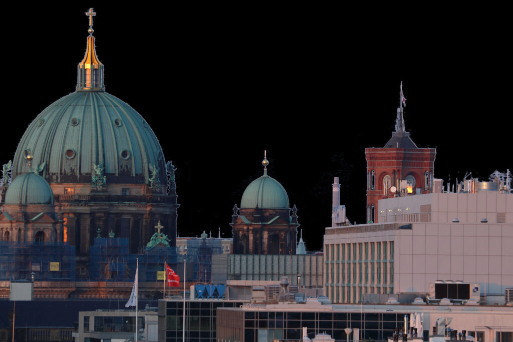
This third image I treat as an additional provided image source to use in Photoshop. Although this image was also shot with a Canon DSLR, I was converting it to a standard sRGB JPG file with the Canon DPP tool, leaving everything at the default settings. I treat the third image as it was coming from a different source that I don’t have any control over. The image has a good quality too, but the view transform is baked in and I don’t have access to a RAW image anymore.
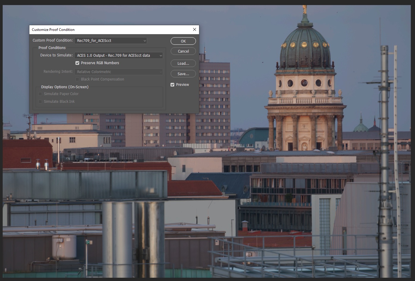
I will start working with the first two plates in Nuke, then hop over to Photoshop and do some work with ACEScct log encoded images in Photoshop with Proof-Colors enabled.
1. Start in Nuke
The starting point is my main ungraded footage plate that I converted to an ACEScg EXR file from a Canon CR2 RAW file. I prepped the shot in Nuke and mask out the main buildings. This result I export as a log encoded TIFF 16-Bit RGBA file in the colorspace ACEScct including the mask to be used in Photoshop if needed. I also export an extra plate with some matching clouds.
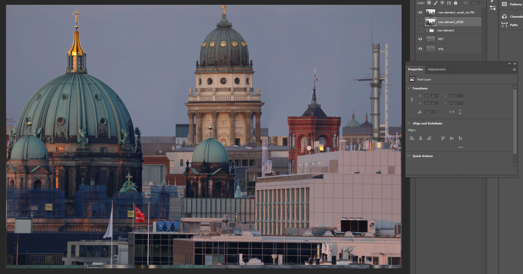
2. Continue in Photoshop
The Proof Setup can be toggled with a hotkey and is being used as the ACES/Rec.709 view transform in this case.
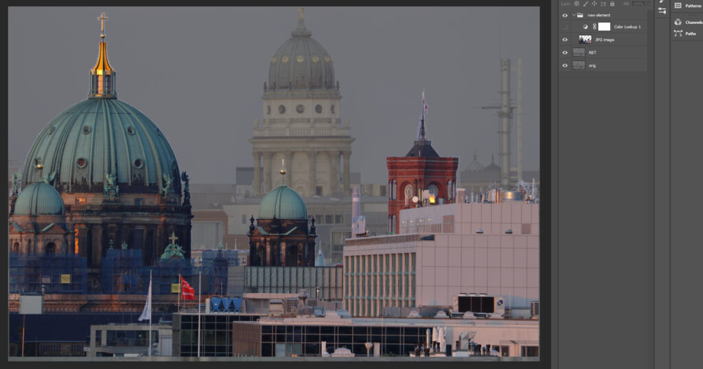
In a first working step I removed the big housing block and moved the church dome to the center of the image. I use the “content aware fill” and the “patch tool” a lot for these tasks, which are my favorite tools in Photoshop for this kind of work.

Note: Doing compositing work in log space is not optimal. The described workflow is more a workaround than a best practice suggestion. Compositing of elements should always happen in scene linear with linearized plates, elements and 3D renderings.
Next I prepared my “new” elements image, keyed and masked out the buildings. As I mentioned it above, for this article I treat this image as if it is only available as a JPG image.
Mixing two worlds
For the next steps I keep view setup “Proof Colors” disabled. The moment I copy the new display referred image into my scene referred log plate I get an obvious mismatch.
Compositing of elements should happen in a scene linear working space environment. Otherwise in some form or another image, edge and other artifacts will appear that you need to fight later on in your comp.
Photoshop expects display referred images to work with, this is what the new element is, but I need to convert it into log encoded scene-referred image data to match my main plate.
The whole Photoshop & ACES workflow is a “big” workaround.
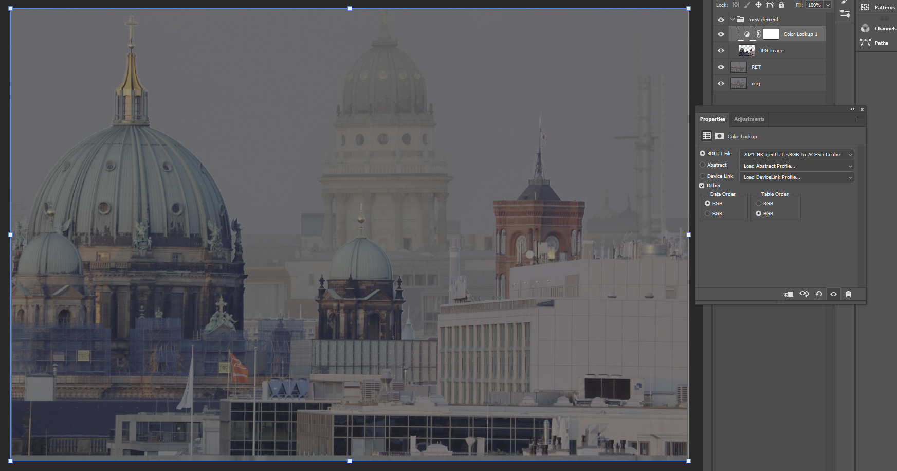
Next step: Use a 3D-LUT to convert the display referred element to ACEScct. These kind of 3D-LUTs can be created with Nuke for example.
- The more “sane” route is to use the 3D-LUT sRGB-Texture –> ACEScct to convert the assumed “sRGB” image to ACEScct.
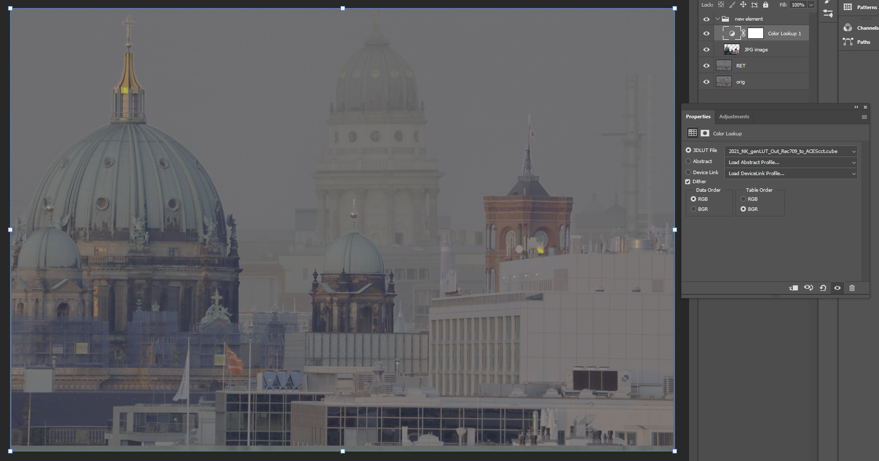
- The visual more appealing but even less “sane” route is to use an inverse ODT to ACEScct 3D-LUT OutRec.709 –> ACEScct. The contrast seems to match better, but the edges might not look that clean anymore.
Using an inverse ODT to convert an obviously display referred element into a scene referred working colorspace is a bad idea most of the times.
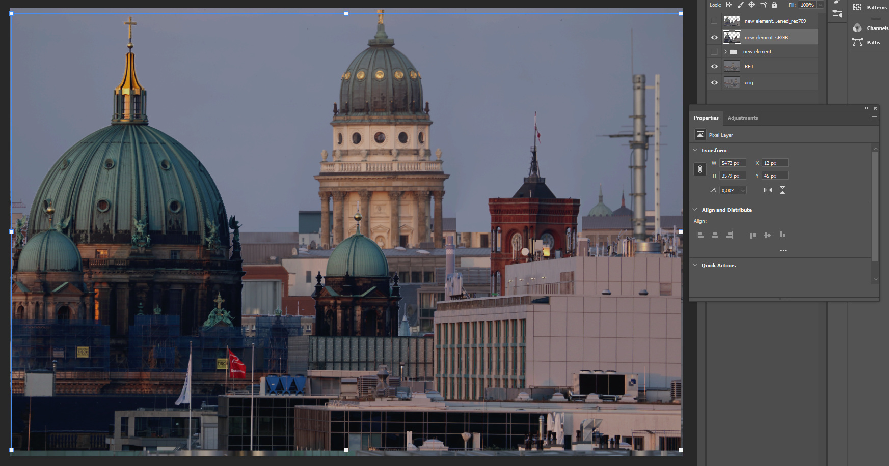
With a quick hit on a hotkey the Proof-Colors are enabled again. But before the new layer will look right, the 3D-LUT needs to be applied to the new elements layer. I had the new element and the 3D-LUT in a group, so I flattened the group before continuing.
Again the second image might feel more “right”, but a closer inspection of the edges will show that using an inverse ODT will end it with unpredictable scene referred values.


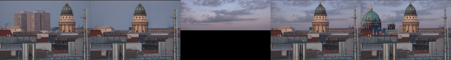
In the next working steps I continued matching the new buildings into the plate and add the new sky as well as a layout. Assuming that all tasks are done, it’s time to export the log encoded TIFF file and load it back into Nuke. The Proof-Colors can stay enabled all the time as the view transform is not baked into the exported file.

When you need to work with this kind of a workflow regularly, it may makes sense to setup some Actions in Photoshop to speed up recurring tasks:
- Converting elements from display referred to scene referred sRGB-Texture –> ACEScct
- Applying the view transform ACEScct –> Rec.709 on a work-in-progress state to share and show the result without the need of using the Proof-Colors enabled in Photoshop.
Thanks again to Sönke Heuer for setting up the whole workflow in 2017 already to work in Photoshop & ACES and creating a little portable .zip file containing the 3D-LUTs and Actions. Sadly the PS-Actions are using absolute file paths, so you need to relink 3D-LUT files each time you use them on a different machine.
3. Back again in Nuke
Lazy as I am, I cropped and graded the resulting DMP from Photoshop and call it a day. The fact that I keyed out the new building elements and did not clean up the edges might be the reason that I end up with some bad edges.

4. Nuke: running into edge artifact problems
The real trouble can start when passing back a layered PSD files to Nuke and start using the elements independently. The layering and edge transparency calculations happened in Photoshop on the log encoded data, but with an assumption by Photoshop that these were display referred images. The zero to one range in the log encoded image has a complete different meaning while viewing it through the Proof-Setup.
The moment I try to re-combine the layers in Nuke, I get a different result than from the entire PSD file. No matter if I linearize the PSD file in the read node first (set the colorspace to ACEScct) or keep it as “raw data” and add a OCIO colorspace node after the merge operations.
The edge problems might not be that visible in the example images so far.
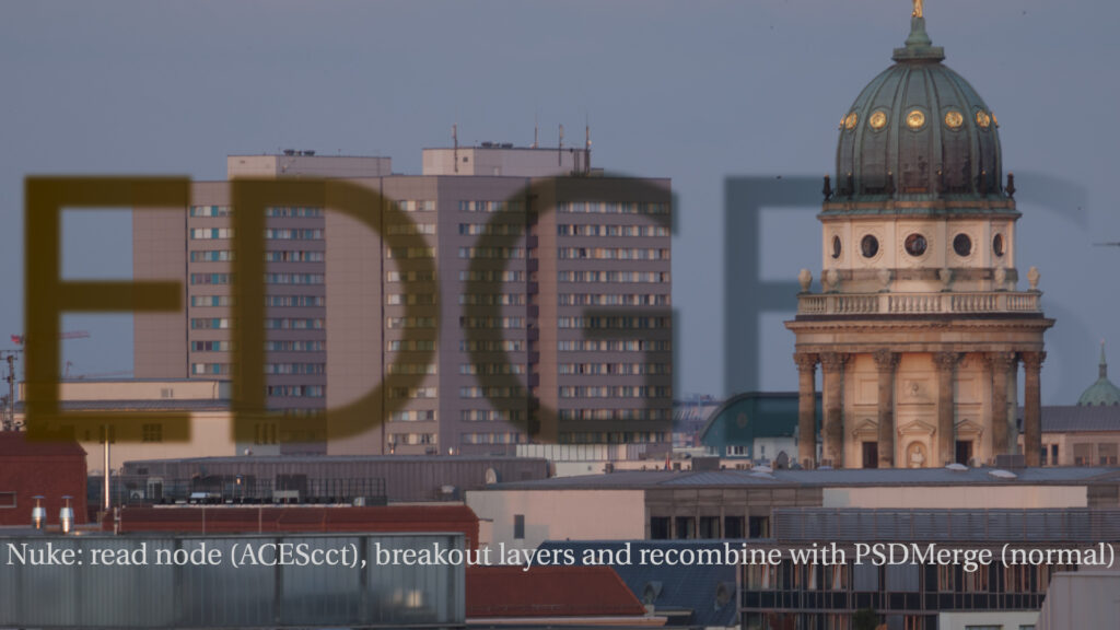
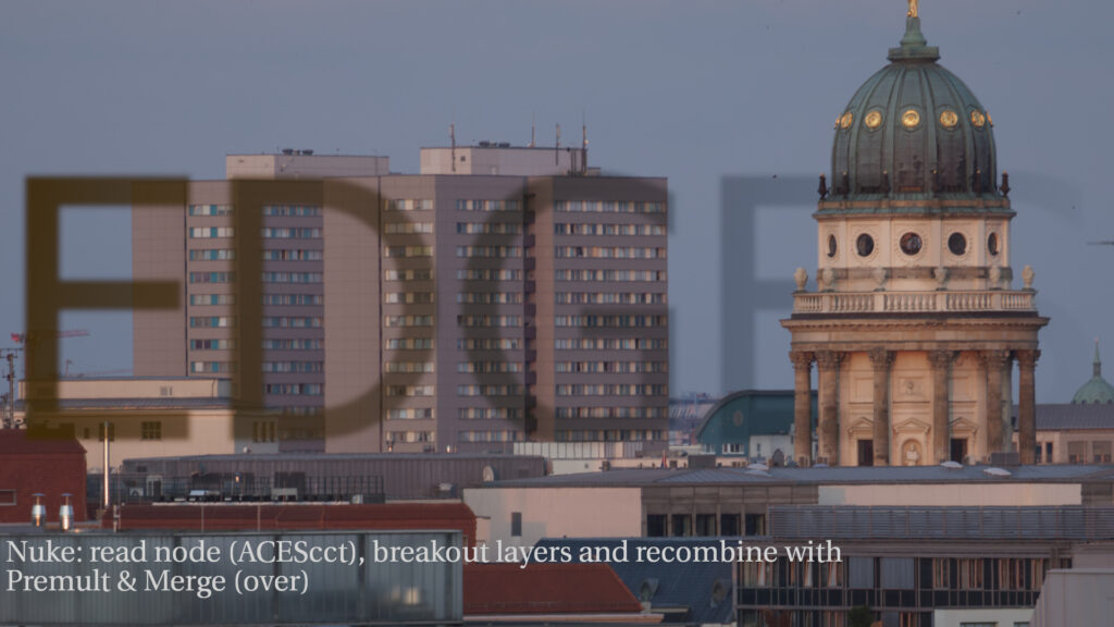
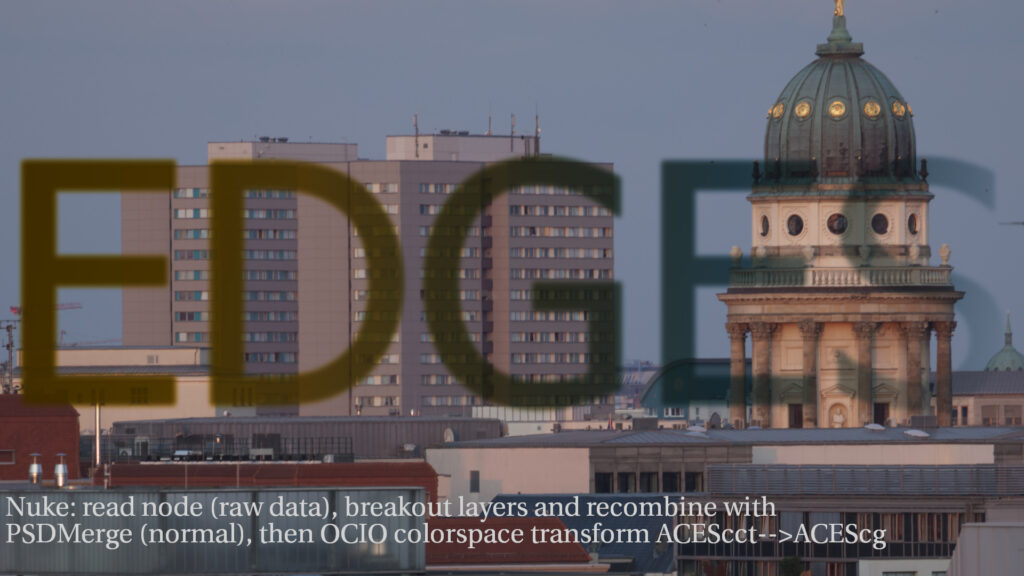
So to make the problems more visible, I simply added a semi-transparent text layer on top of the initial background image in Photoshop on the log image. On the left side is the Photoshop result and on the right side I show two ways to use the layers back in Nuke: linearizing the log encoded data or keep it in log (like in Photoshop) and linearize after the merge operations. In both cases I am not able to match the result from Photoshop. Usually if there is a mismatch, it is about a colorspace linear to sRGB transform that needs to be applied or taken off before the merge operation. But in this case I did not get a match. If someone can point me to a solution to get a perfect match, please let me know.


5. Conclusions
Again, I am not a matte painting artist, I can only judge the whole Photoshop & ACES workflow from the viewpoint of a compositor. At times this workflow can be very useful, as I showed in the first article, but overall it is a “bad” workaround with many compromises. Photoshop with OCIO support would be a great improvement for creating DMPs. I try to use Affinity Photo as an alternative app for these kinds of tasks as often as I can.