Test the “best” HDRI in Blender 2.91beta and a render an old Ford Mustang model.
After picking the best HDRI from the previous comparison in the article 2.4.3. Eliminate Variables, the next step is to see how well this HDRI can light a scene. So I setup a scene in Blender&ACES and hit off some renders. This time, instead of my usual colored cubes and spheres, I wanted to render a more “fitting” object into a photographed background plate that I shot shortly after I took the brackets for the HDRIs (I should have taken a longer lens with me for a better background plate, but I had only the wide lens with me). I received a tip for free car models that are available at the Wire Wheels Club website. In case you want to skip the process of setting up all the materials for yourself like I did, the models are also available for a small fee as a finished Blender scene at gumroad. I bought one and will use it for the renderings later, but first there are still some steps missing before setting up the scene in Blender.
The goal for this article is to render a good “starting” point for a compositor like me.
My “look” reference – one interpretation of the captured “scene”
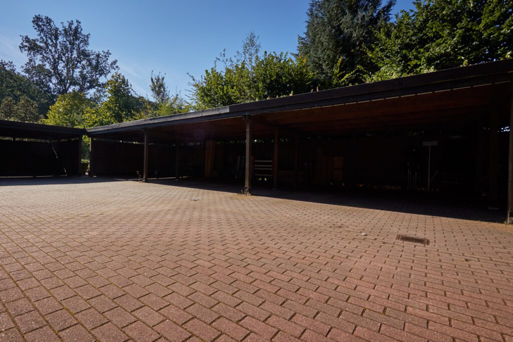
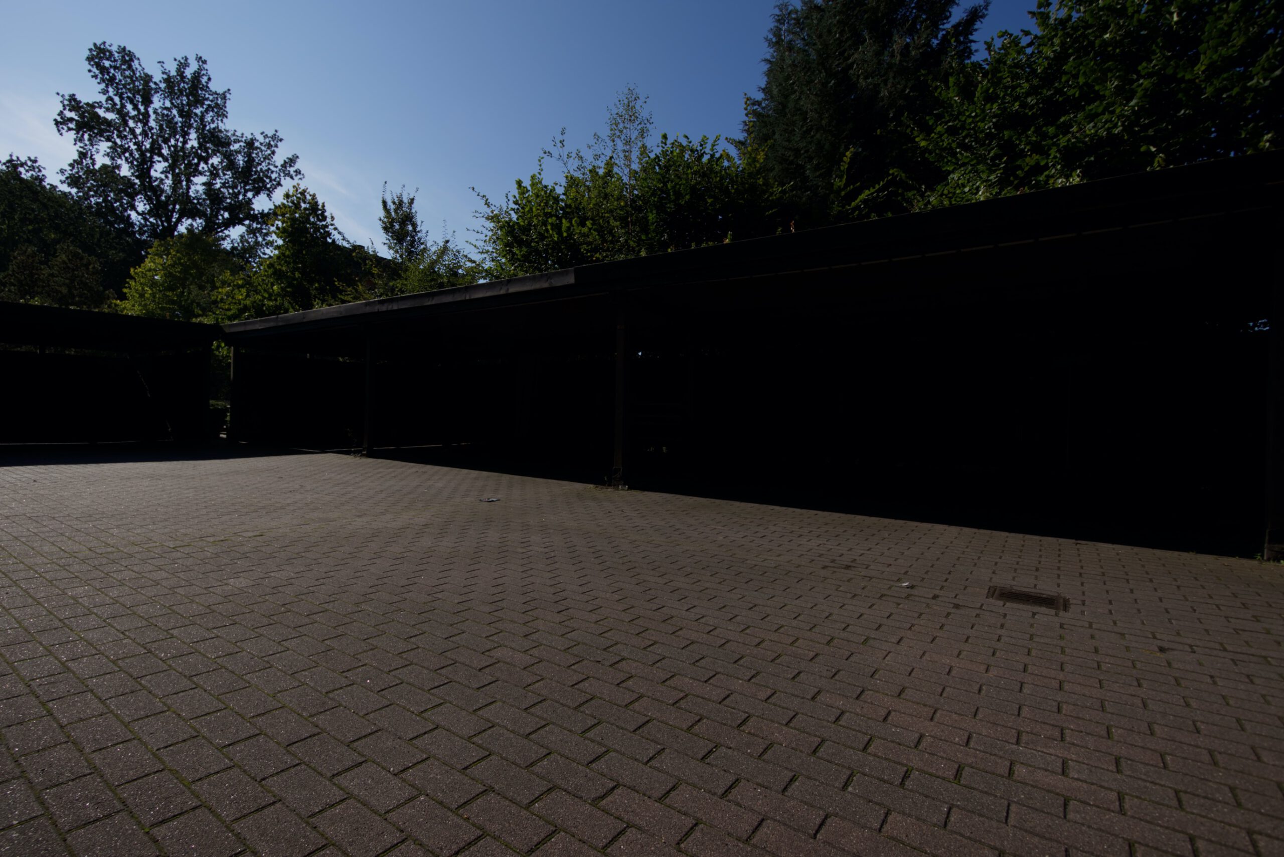
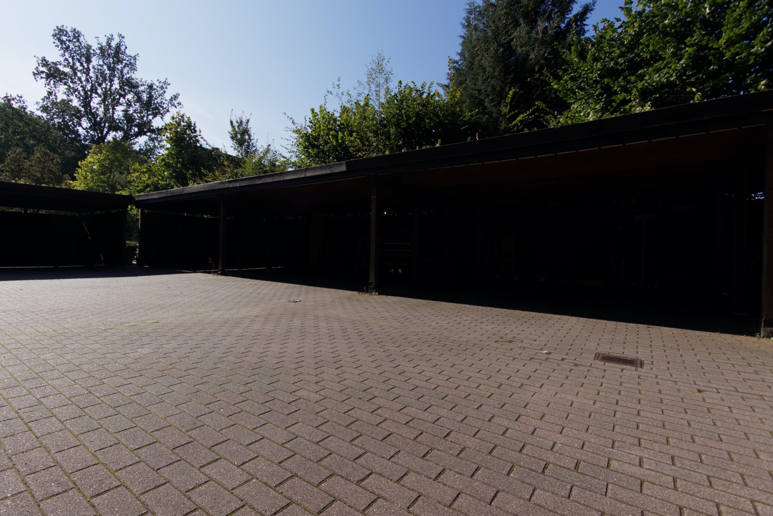
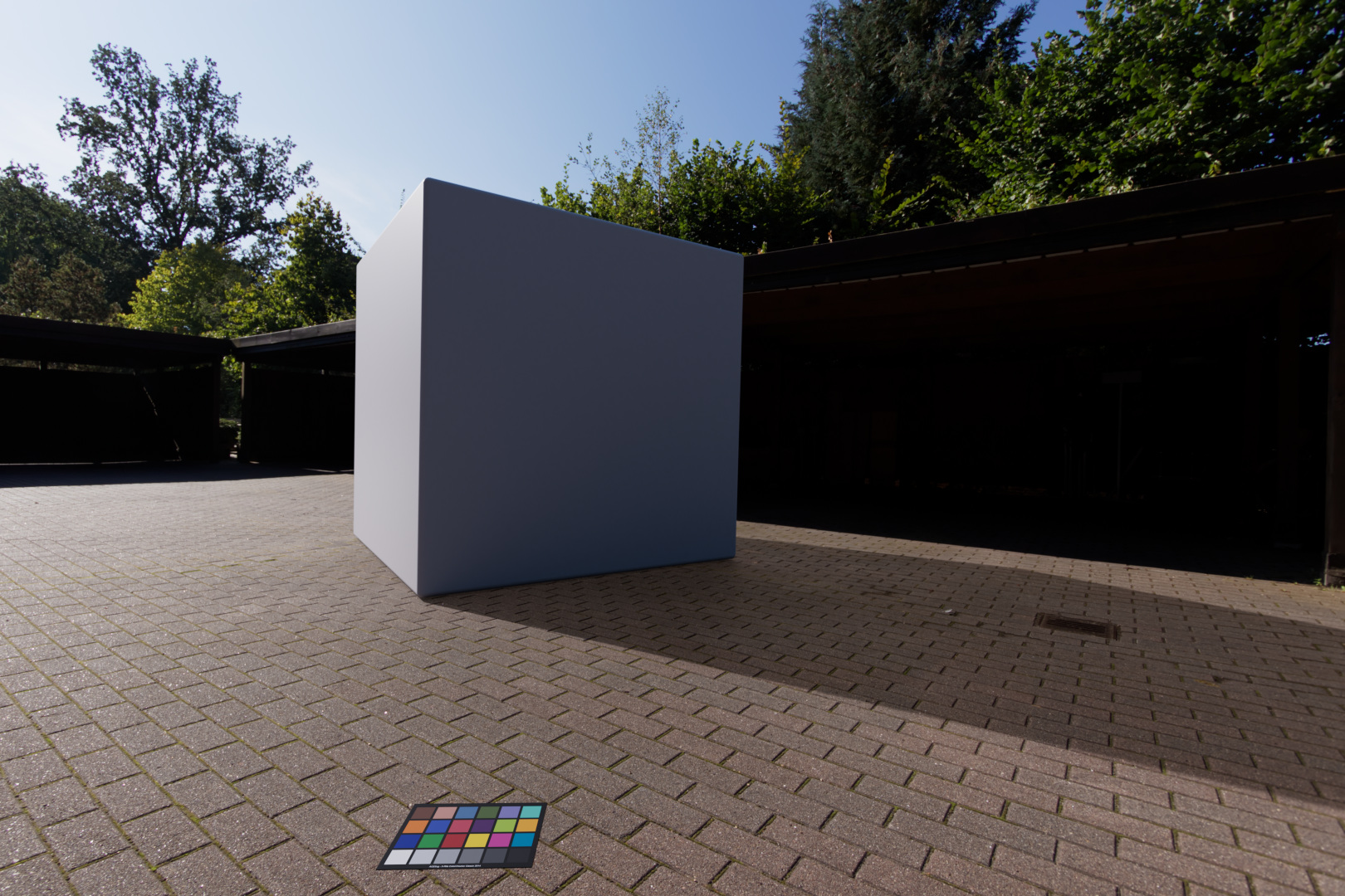
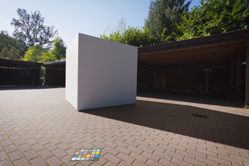
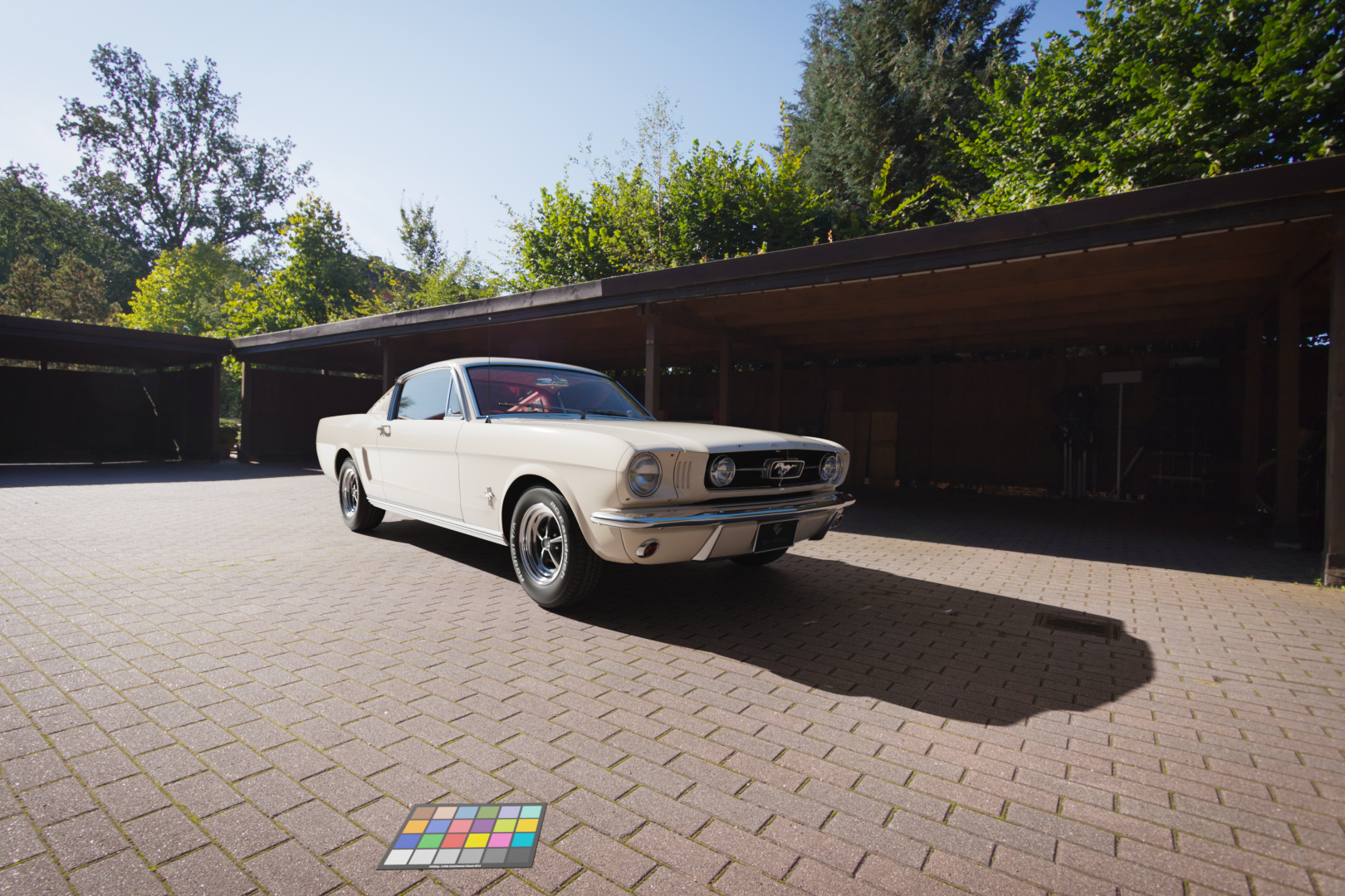
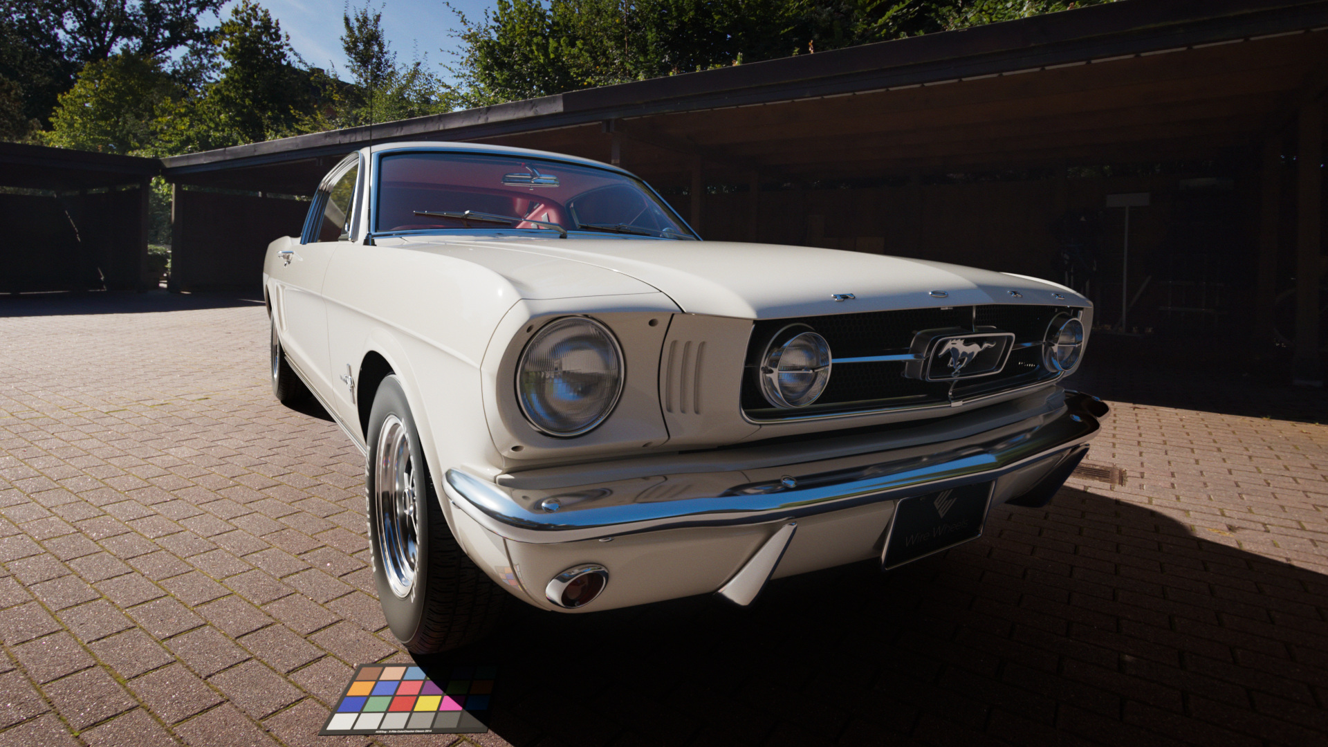
This is the background plate that I chose to place the 3D-car model “inside”. I pre-graded this empty plate in Capture One, set an overall look, warmed up the ground, darkened the sky and took out a bit of the “very” green foliage in the background. This is an interpretation of the “scene” that I captured with my Canon 7DMKII. This is how I remember it looked on that day, standing there and choosing the angles for the plates and imagining a car would be standing somewhere in the sun. I am pretty sure I would grade this image differently if a car would have been present at the time, because I would focus the grading on the car and the background together and not only on the empty background.
Please refer to the article “Display Referred vs. Scene Referred” for more information why grading should be always the last step in the process after the comp and not before.
Matching the background plate and the HDRI to each other as best as possible
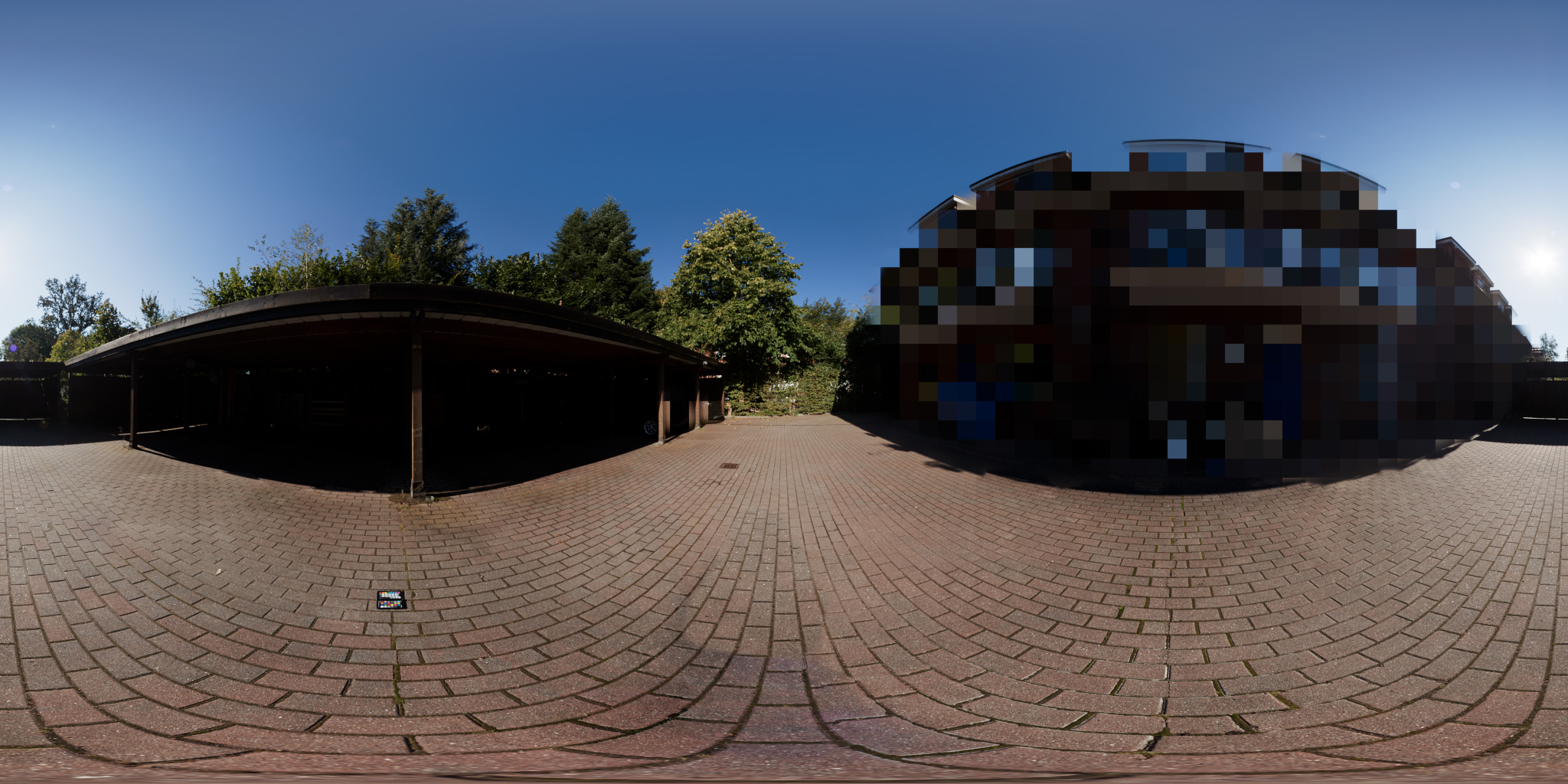
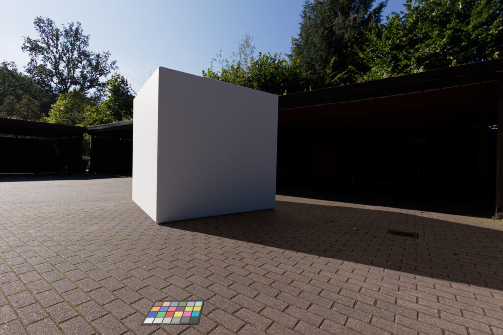
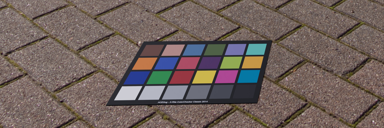
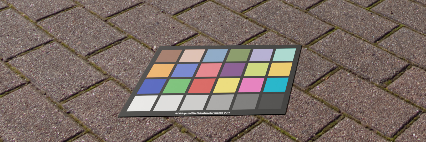
The color chart for the HDRI and the back plate was placed in the sun facing the sky. The balanced plates are therefore quite dark as the mid-grey patch of approx. 18% was facing also the direct sunlight.
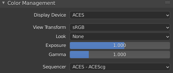
Although both the back plate and the HDRI are balanced to the reference ACEScg color chart, even in this dark state the colors don’t match too well. The sky of the back plate is too magenta and the ground of the HDRI is too red/warm. But they are already quite close. With two Hue Correction operations in Nuke it was an easy matching process to get both images closer to each other. Also exposing up both images one stop is helping further get a more decent image to look at. The exposure correction is seen here on the following images, but actually I was adding this correction later in Blender “Exposure = 1.000“before the view transform and in Nuke when checking the renderings.
I will add the exposure step later, because in this way my color chart is kept still at approx. 18% for the mid grey patch through the process.
Setting up the Blender scene and first render
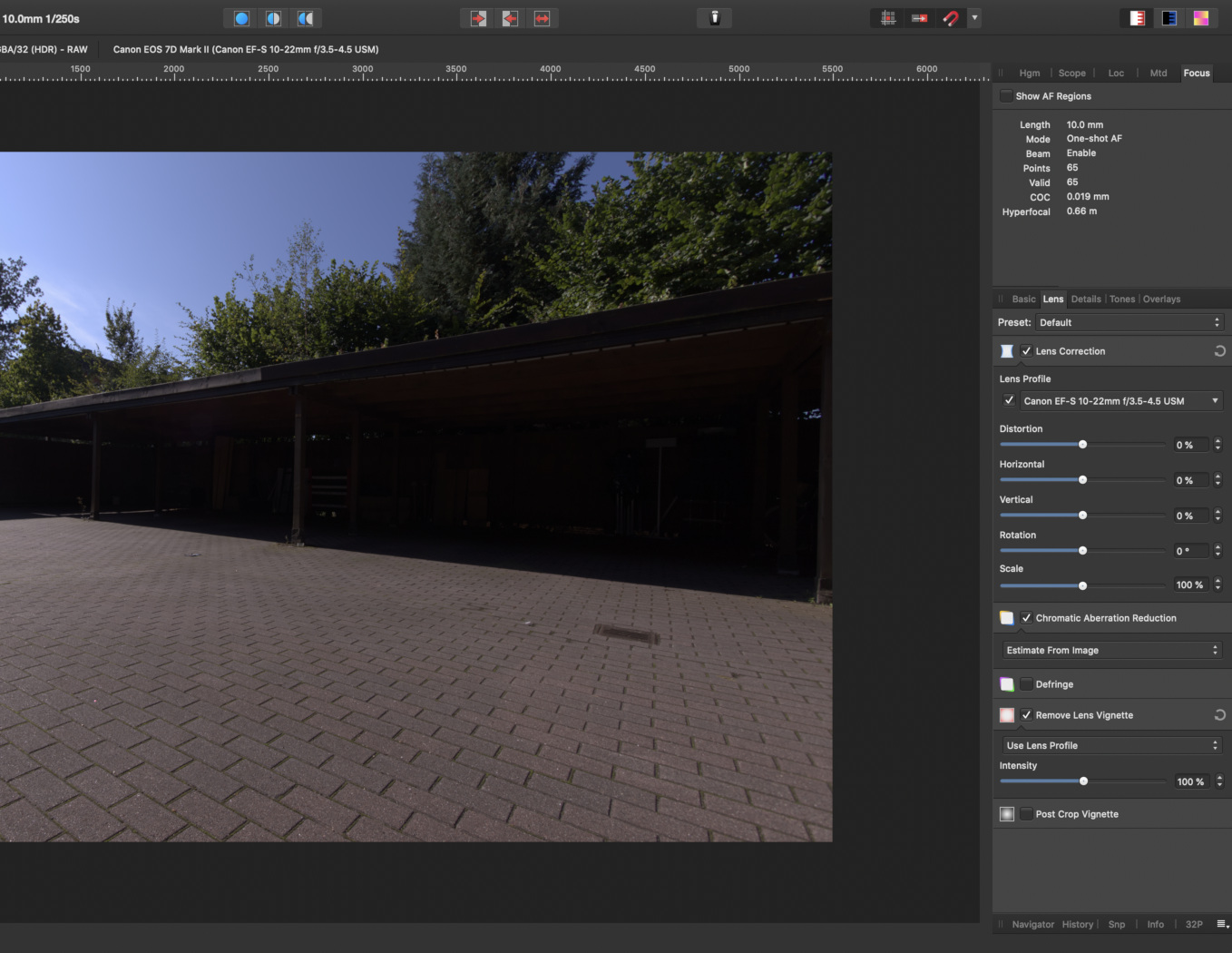
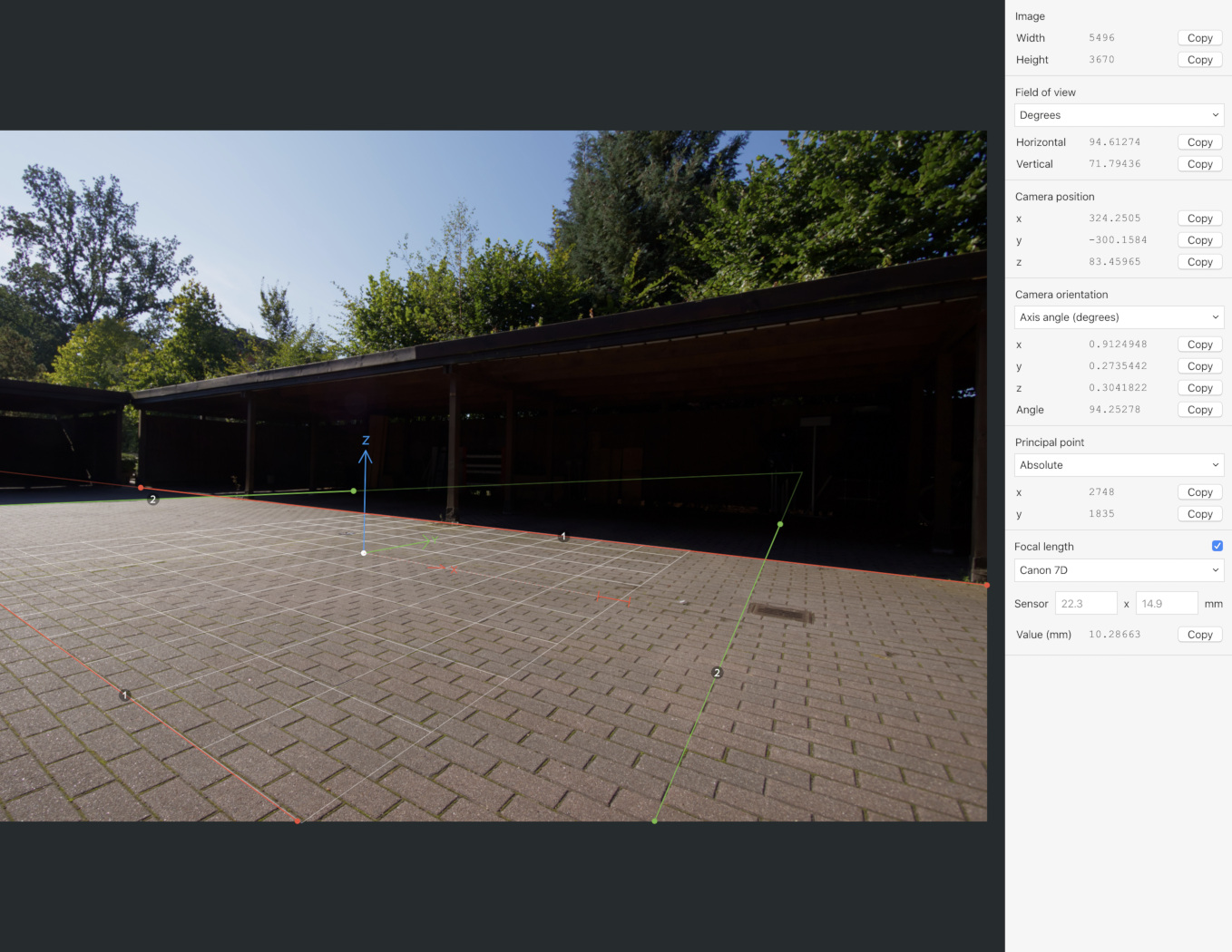
The back plate was converted from Canon RAW to ACEScg EXR with Affinity Photo. In the RAW development process I was also able to take out the lens distortion and the lens fall off, both with the help of the lens data that is provided in the RAW converter of Affinity Photo. Then I used fSpy to calculate the camera position and loaded the result into Blender.
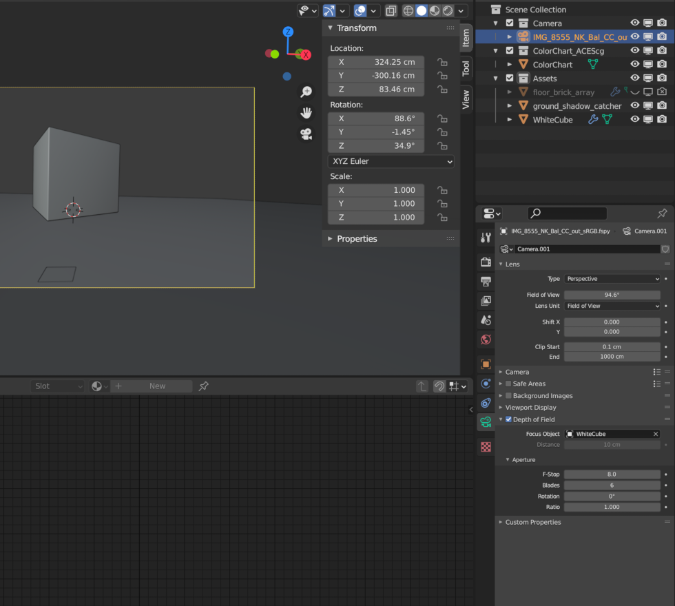
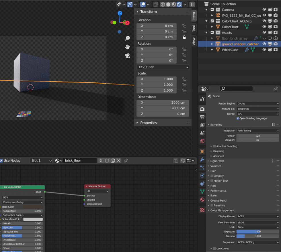
For the first render I only use a white cube and a ground object that acts as a shadow catcher. The cube has a principled shader with a albedo value of 0.9 or diffuse white and the ground object has an average albedo color of the ground tiles of the HDRI. The scene is lit exclusively from the Canon f-stop 8 HDRI.
The shadow that the sun casts seem too much light or faint for this scene. Also the white cube still looks a bit “dirty” grey instead of white. The Canon HDRI f-stop 8 was clipping in the “sun” around a scene linear value of approx. 25.000. So it seems the sun is simply not bright enough yet to cast a dark shadow that matches the scene. The second HDRI with f-stop 22 didn’t clip in the sun and had maximum scene linear values around 115.000. So, let’s try this one for a test.
This HDRI I did not want to use any further because of artifacts in the shadow areas, as it was underexposed. I showed the artifacts on the first part of this article 2.4.3. Eliminate Variables. But the shadow of the rendered cube is looking much better already and the sun facing side of the cube looks like a white object that is hit by the sun directly, it looks “white”.
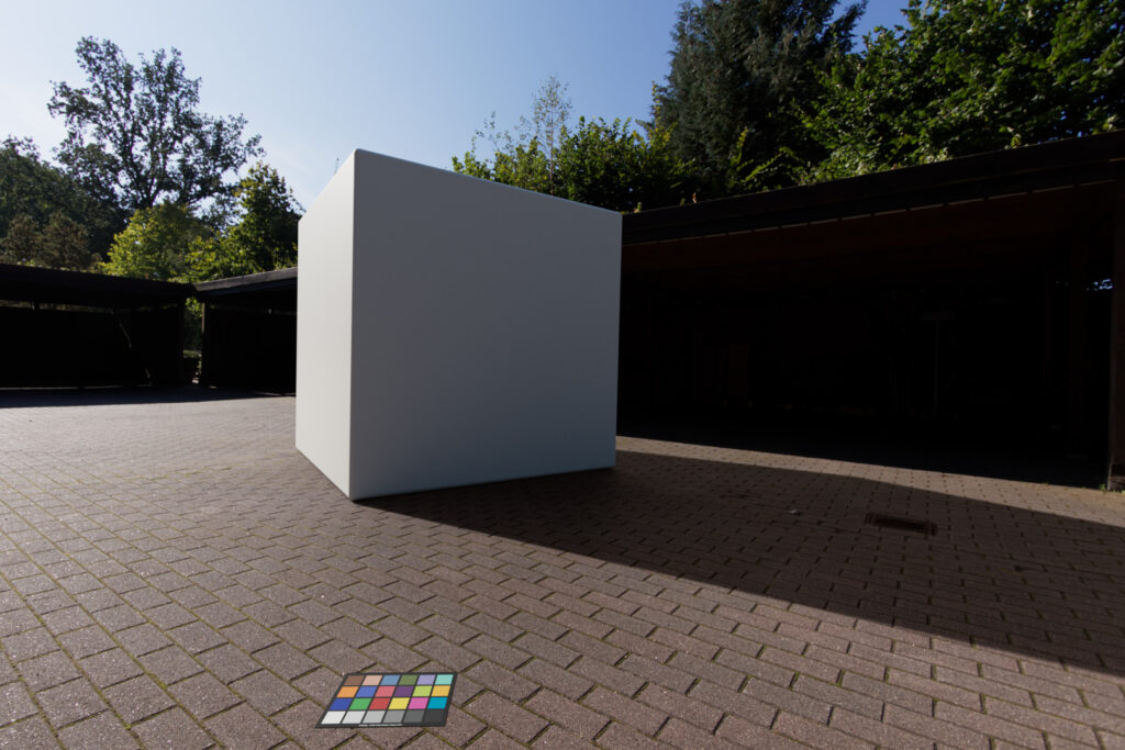
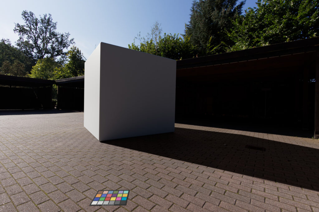
Question: Which shader is best to pick for the reference color checker?
First I need to say, I don’t know which material properties the color checker should have. I was reading and asking around. The answers ranged from: “only use a diffuse shader or use a principled shader without any specular (which looks the same as the diffuse shader only in my case).
Thanks to Chris Brejon to point me to this article: “Everything is Shiny“. Blender is using by default the principled shader. I use the shader also for the color checker and raised only the roughness and set it to 0.8 from 0.5 which is the default value.
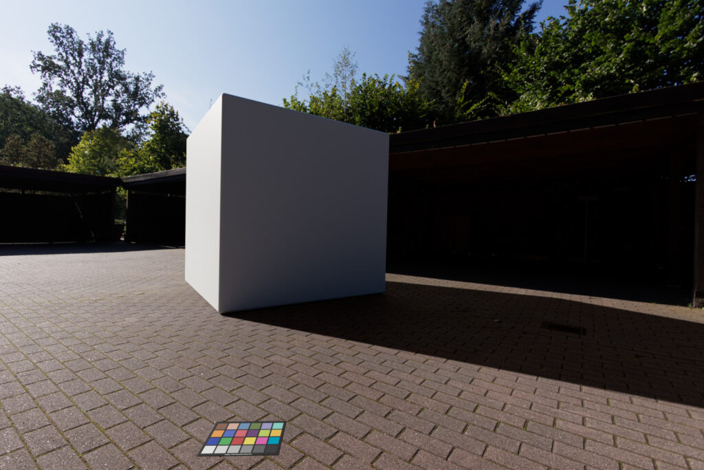
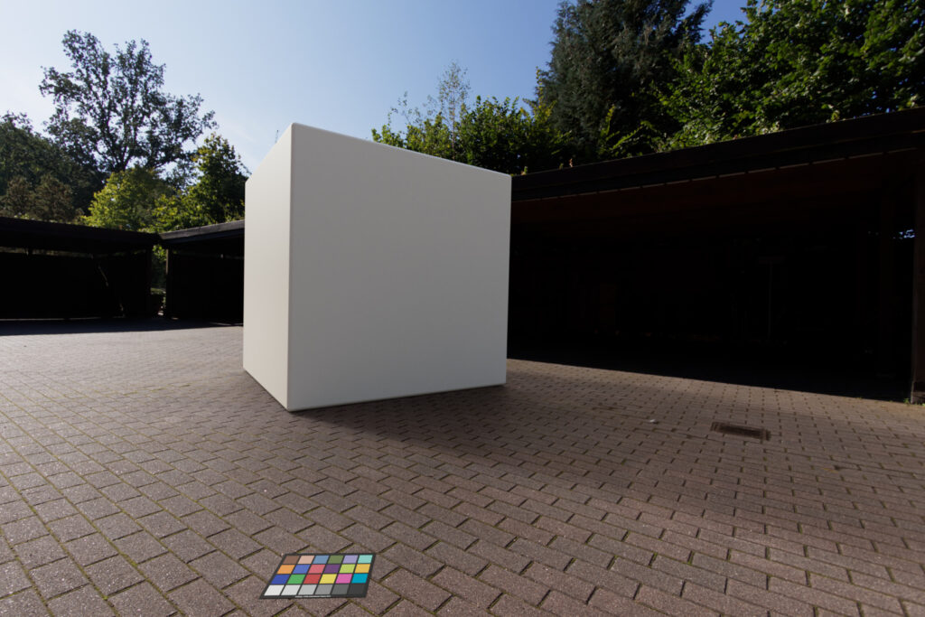
Second, if I stare for a moment on the next two images, at least my “eyes”tell me, that the stone tiles on the second image under the rendered chart are brighter. But they are not really, both backgrounds are nearly identical and only slightly affected by the shadow catcher object. The eyes get so easily fooled, that’s why I render a color chart in the scene. In the next render steps I will balance the render result to the 18% mid grey in the same way I balanced the plate and the HDRI to each other.
Calculating the shadow intensity
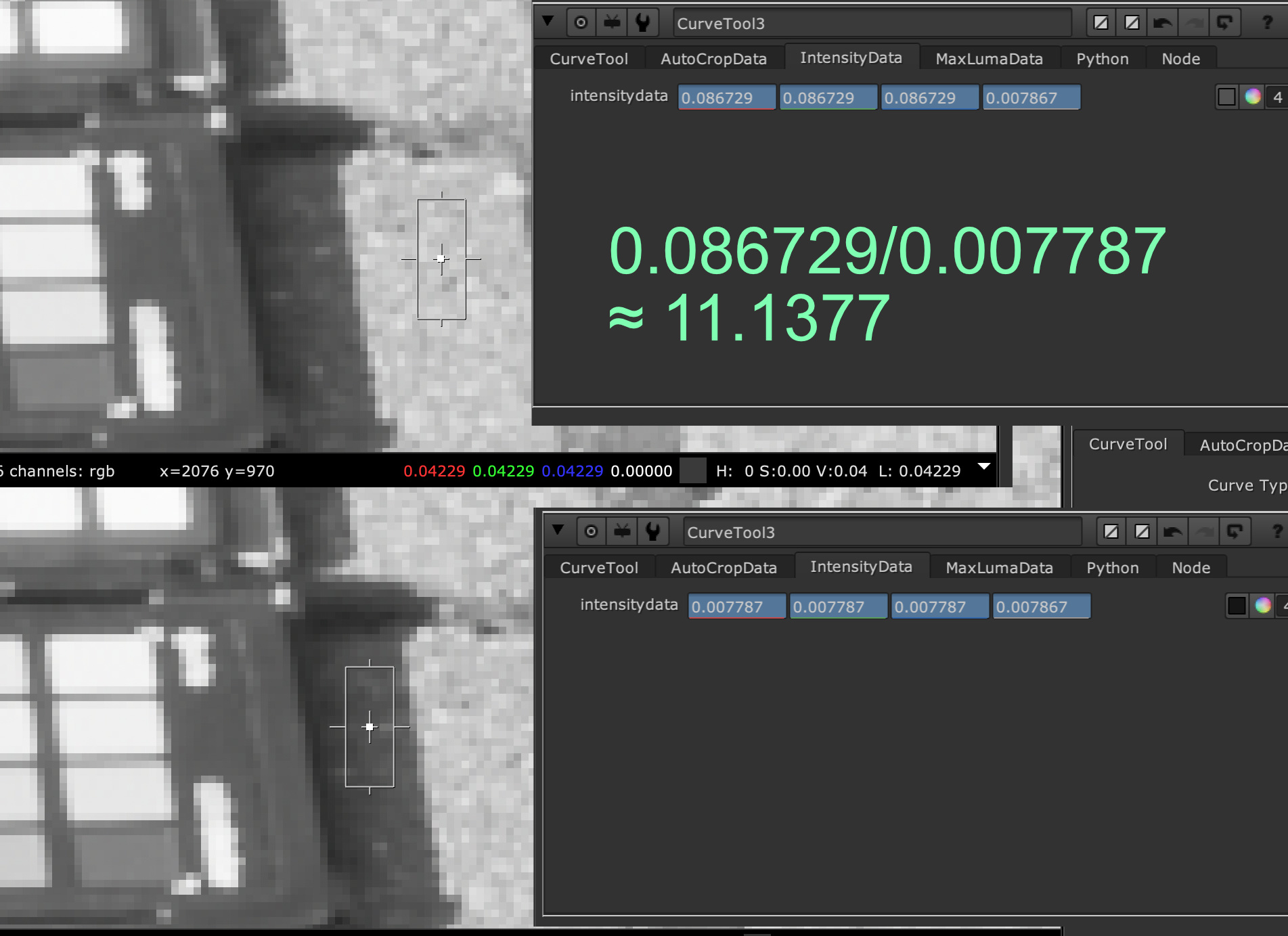
Before I render the next round of tests, I want to try to get a better contrast of the white cube and the shadow that it is casting. For this I try to calculate how dark the shadows of the shadow catcher object roughly should be.
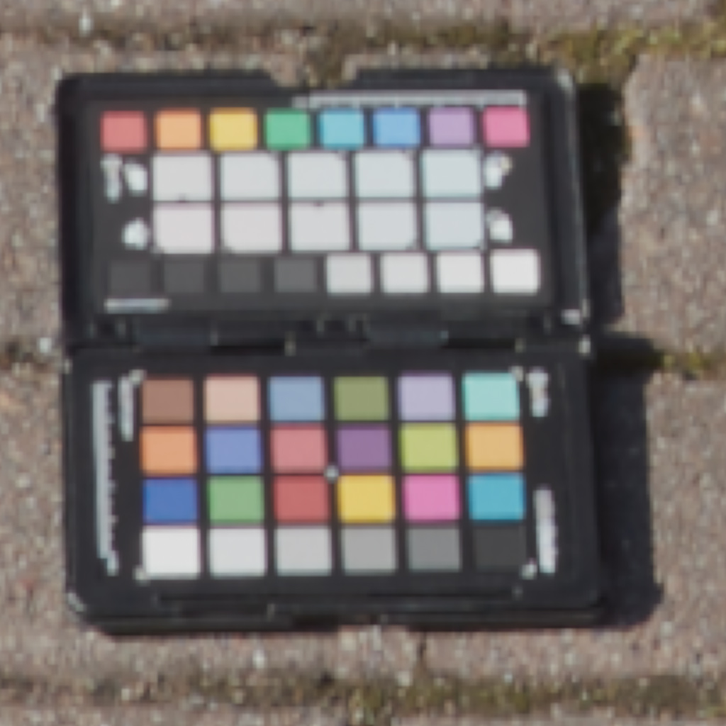
With the help of the Nuke “Curve Tool” I calculated some rough ratios (Avg. Intensities) between certain area where the ground stones are sunlit vs. have a cast shadow by the tripod legs or the color chart itself. Actually I measured several areas in the plate and the HDRI.
The sun to shadow ratios varied between:
- 1:7.34 (sunny ground vs. tripod shadow in the color matched HDRI)
- 1:8.51 (sunny ground vs. camera body shadow in the color matched HDRI)
- 1:11.08 (sunny ground vs. color chart shadow in the color matched HDRI)
- 1:34.00 (sunny ground vs. shadow area under the car port in the color matched HDRI)
- 1:30.00 (sunny ground vs. shadow area under the car port from the back plate photography)
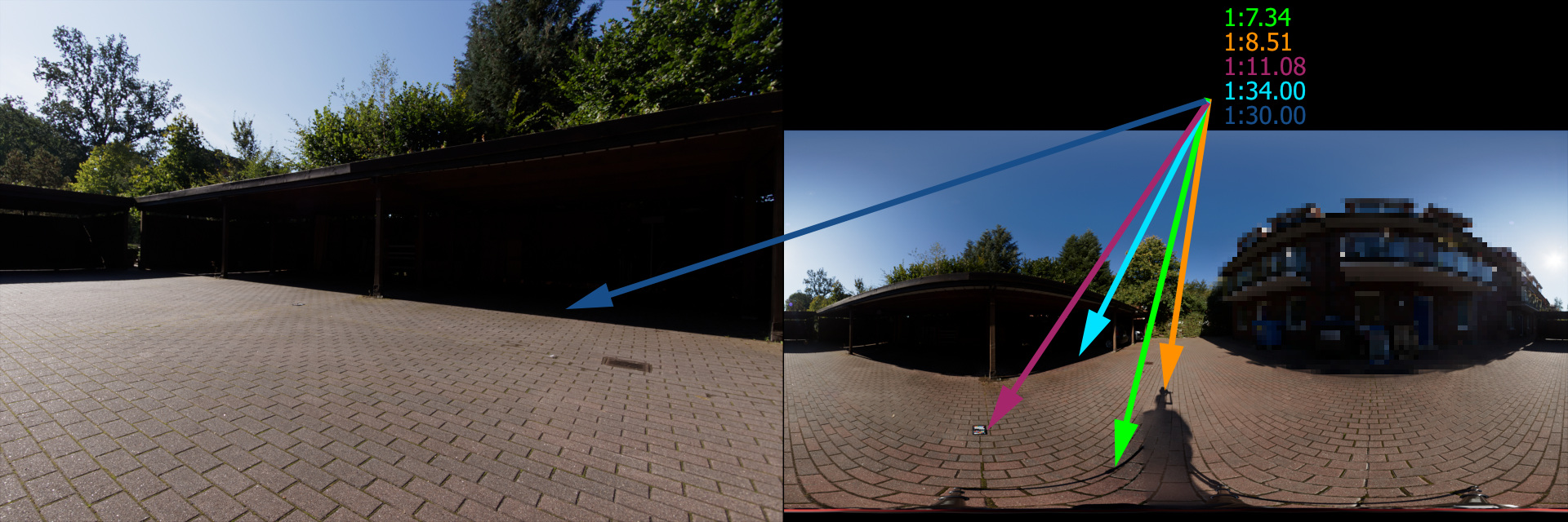
This results in an average ratio of around 1:17. So I am getting a rough idea how dark the shadow (or how much the shadow catcher should darken the background plate) from the rendered cube should be.
Tweak the sun and hit off a second render
As I want to use the Canon f-stop8 HDRI because it has a better quality overall, I had to tweak it to achieve the same dark shadows from the cube onto the ground as with the f-stop22 HDRI. From now on, I also balanced the rendered result to the 18% patch of the color chart for the objects and the shadow pass as well.
The first render (1.) created a sun vs. shadow contrast ratio of only around 1:4.51. The unclipped HDRI f-stop 22 (3.) was around 4.5 times brighter, so I intensified the core center of the sun from the f-stop 8 HDRI with a soft circle mask and multiplied it by 5 and hit off another test render (2.).
The result of modified f-stop 8 HDRI (2.) looks now very similar to the “unclipped” sun of the f-stop 22 HDRI (3.). If you look carefully you can see that the shadow of the cube moved already a bit, because the first HDRI with f-stop 22 (3.) was taken roughly 12 minuets earlier than the second HDRI with f-stop 8 (2.)
Just for fun I rendered also with the HDRI from the Theta-Z1 in two variations. The sun in this HDRI clips far earlier and reaches a maximum scene linear value of around 112 after the balancing step. The result (4.) looks very dull and the shadow very soft like on a lightly clouded day. This cube does not fit into the scene. The same trick that I used with the Canon f-stop 8 HDRI (3.) works of course also here. As the maximum values were so low, I need to multiply a small sun core in the HDRI over a mask with a factor of 1.000 (112*1.000=112.000) to reach a similar brightness and shadow contrast like the Canon HDRI renderings (2.) and (3.).
Which one is the “winner”?
To make it easier to compare the rendering results, I put the images from above into a one sequence. Starting with the worst result, the Theta Z1 image (4.) with only a HDRI balancing step, followed by Theta Z1 image (5.) with an enhanced sun core. This result looks then nearly identical to the Canon f/22 HDRI (3.) and the Canon f/8 with the enhanced sun core (2.). At last comes the Canon f/8 with the clipped sun (1.) which results in a low contrast and too bright shadow.
Actually the middle three could all work in this stage. I will stick again to the Canon f/8 HDRI with the enhanced sun, as this HDRI has the best overall image quality. Especially when it comes to visible reflections of the environment in an object, the not so good quality of the Theta Z1 HDRI or the underexposed Canon f/22 HDRI could lead to visible artifacts.
Setting a first look
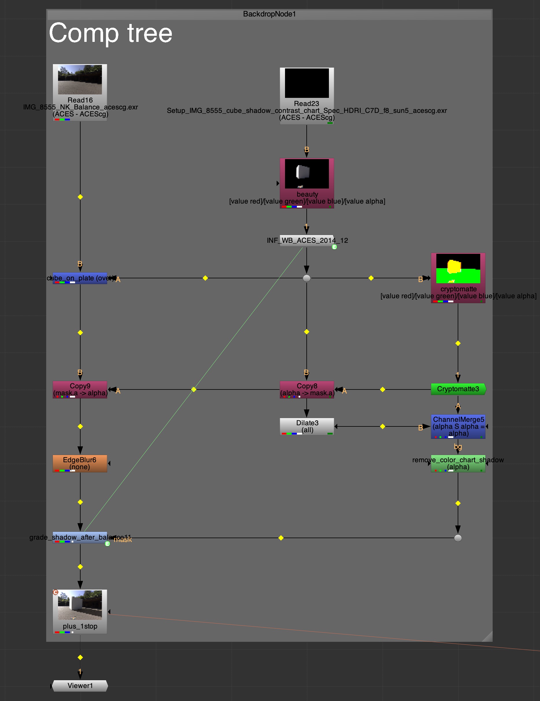
The very simple “comp”, contains only a balanced A over B merge operation plus a balance correction for the shadow pass. Next, I added a plus 1-stop exposure compensation for the 18% grey patch that was measured in direct sunlight. This puts also the 18% grey patch a bit over the sRGB middle grey with a value of RGB 144. This be be measured here on the website on a MacOS with the “Digital Color Meter”.
But the image doesn’t look very pleasing. The shadows are pitch black, the contrast is quite high and although it was a bright sunny morning, the image does not look like it. So its time to add a first “look” to the image.
To keep it simple I only use a Nuke OCIO-CDL-Transform and a small darkening of the edges of the image, similar to the lens darkening that was present in the RAW image plate, but which I took it out in the RAW development process.
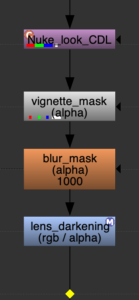
I also tried for fun to apply the ACS-CDL values in the Blender Compositor, but I cannot find the saturation value, plus I am not able to load a .cc file and have to enter the values by hand. That is not very convienient, but I would do my comp anyway in Nuke or Flame.
With this look applied “after” the comp, now it’s time to replace the cube with a car model from Wire Wheels Club.
Time to render something else than a cube
I bought a finished .blend scene file from a 1965 Ford Mustang. It comes with a bunch of textures and it is ready to be rendered in Blender/FILMIC. There are some steps neccesary to get the scene ready for Blender/ACES. I converted all the textures from .jpg to .exr (ACEScg) in Nuke. I could also used the sRGB-Texture IDT in the shader tree, but I decided to go with pre converted textures.
Another tool I found (for Windows only and I use MAC) is a texture conversion tool called “PYCO Image Colorspace Converter” from MrLixm.
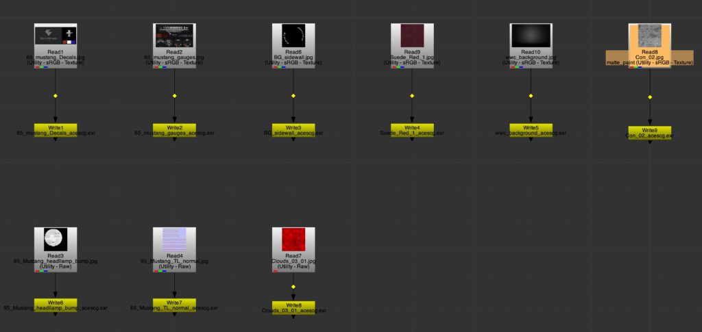
But even more important, Blender does not automatically convert RGB shader values for the diffuse color from linear-sRGB to ACEScg. So I did this also manually in Nuke with a constant and a colorspace node.
For more information about the importance of converting your diffuse colors when you are working in a different color gamut than linear – sRGB/Rec.709, please refer to the article Understanding Gamut with ACES and Blender.
Converting RGB shader values can be also done this with Colour Science for Python. Here is the code, but I must admit I noted this down one day and saved it, but I don’t know where I found this snippet in the first place.
Conversion of RGB linear sRGB/Rec709 to ACEScg values
import colour
### set linear sRGB value
input_linear_bt709_RGB = [0.500, 0.000, 0.000]
### convert to ACEScg
output_linear_ACEScg_RGB = colour.RGB_to_RGB(input_linear_bt709_RGB,colour.RGB_COLOURSPACES[“sRGB”],colour.RGB_COLOURSPACES[“ACEScg”])
###print converted result
print(“Your handy dandy ACEScg AP1 linear RGB values are: {}”.format(output_linear_ACEScg_RGB))
Your handy dandy ACEScg AP1 linear RGB values are: [ 0.30655891 0.03496704 0.0102315 ]
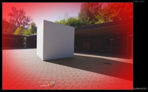
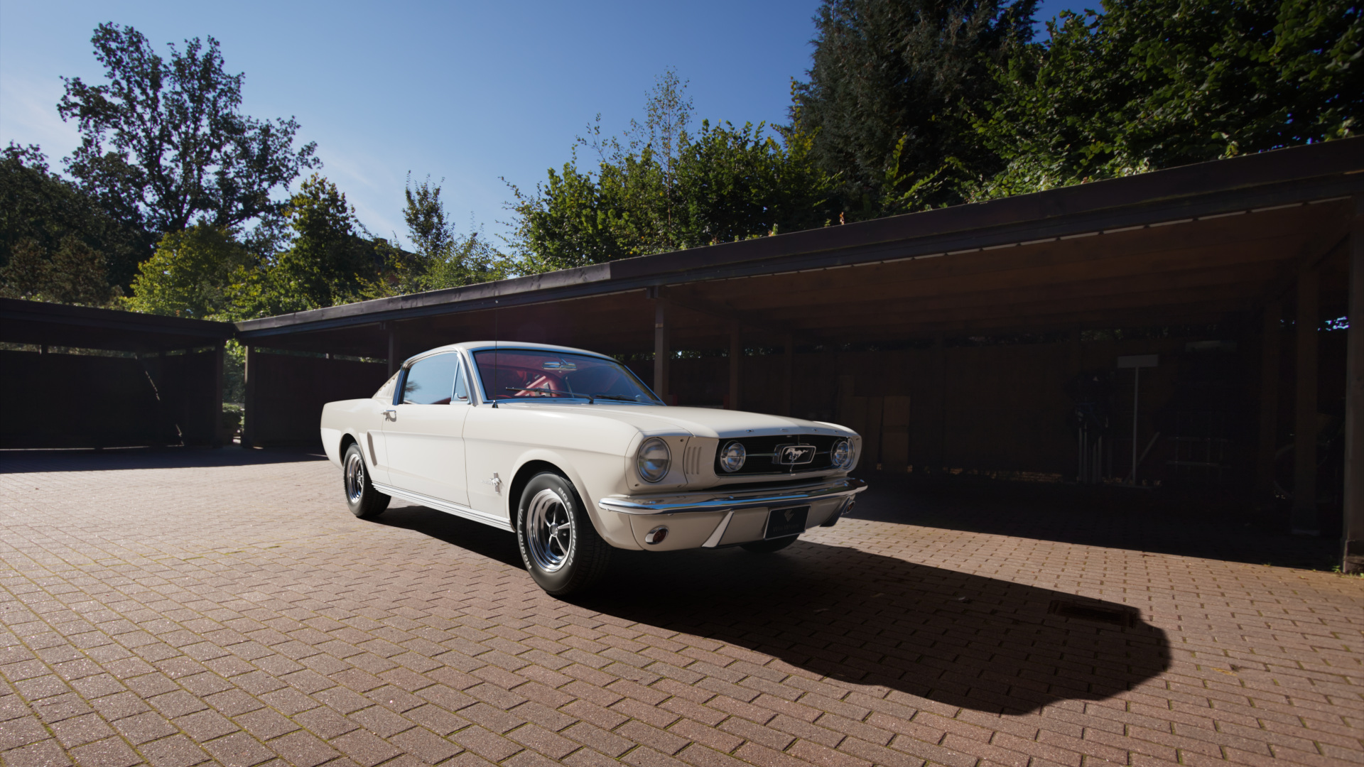
Finally, here is a quick render, just placing the car into the scene and hit render. The simple Nuke “comp” tree is the same with the CDL “look”.
My final “look” and looking back at the beginning
Before finishing up this article, I wanted more or less re-create the “look” from the very beginning, the empty background plate. The grading with the car ended up slightly different, because I had on object to focus on my attention. In the very last step I adjusted the framing to a 16×9 HD output.
In my opinion now it would be the right moment to start with the actual compositing work and finish this shot.

Conclusion
The goal of this article was to make use of the “winner” HDRI from the previous article and get a decent result directly from the renderer, while using very little or no compositing effort to create a realistic looking image. You tell me if I succeeded.
I am happy with the overall result, but somehow not so much with the car shader itself. I am looking into car paint shaders (including OSL-shaders) in Blender for a while already and I want to write about the results in a future article.
The whole HDRI creation and background plate shoot was really a “dream” demo setup and does not reflect production reality at all.
In a real production, there is usually no time to shoot background plates and HDRIs at nearly the same time to even at the same spot. Moving clouds will not lead to such a stable result between the background plates and the HDRI RAW brackets. Lens data of background plates are often hard to get and the list of problems that might occur can go on and on.
And even if everything goes right, at the end the client might mislike the location or how the car looks in the final compositing. Then a lot of adjustments have to be made in composting and grading and these changes lead often to a less realistic result over all. But that struggle is part of the process.
Some take away working steps that might help:
- Separate the technical setup/comp from the creative look part. First get it technical right, then make it look good.
- A “look” is an interpretation of the captured “scene”. A “look” should be planned and defined in the beginning of a production, but applied only at the end of the comp process.
- The final “look” of the image should be judged on a reference monitor for a specific display or projection. If an output for a different display is needed, a trim pass should be done on that display to really judge how the result will look like.
Resolve HDR files
I am constantly researching HDR content on my devices. Here is a Resolve Studio trim pass grading for ST-2084 (1.000 Nits with D65-P3 Primaries) of the two Nuke comp stills.