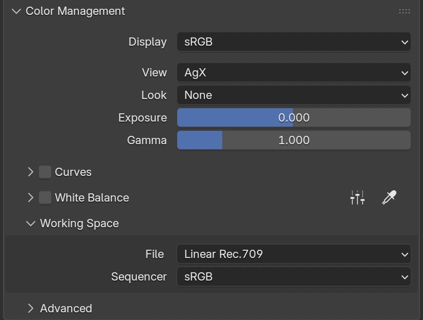
My favourite new feature in Blender 5.0 is that the active working color space is finally exposed to the user. The “factory-default” settings when installing Blender 5 fresh are shown here, tell me that the working color-space of this .blend file is“Linear Rec.709”.
Also, now you have the ability to change the working color space manually for the active .blend file (or save it as a startup default). This opens new possibilities to render in a larger working color space than “Linear-Rec.709” without having to use an external OCIO config or alter the config that ships with Blender.
Additionally, Blender 5 adds native support for ACES 1.3 and ACES 2.0 next to AgX, Filmic, Khonos PBR Natural and Standard.
Before, when working with external OCIO configs, the working color space was set to the specified color space in the OCIO config automatically:
- AgX (variants) to Linear-Rec.709
- OpenDRT and T-CAMv3 to Filmlight – linear-E-Gamut 2
- ACES 1.2, 1.3, and 2.0 to ACEScg.
This Blender update is a good fit for my latest posts in the section Numbers and meaning, because as soon as you change the working color-space to a different set of primaries than the ones of Rec.709, the meaning of RGB values in light, shaders, and texture will change. And therefore, the image results will change too.
For this first article, I want to stay with the default working color space “linear-Rec.709”, but to simplify the image processing chain even more, I switch the view transform from “AgX” to “Standard“. This means that only an inverse EOTF of the selected display device will be applied to the image data as soon as a format like JPG, PNG, or TIFF is selected as the output format. EXR outputs are not affected by the selected view transform.
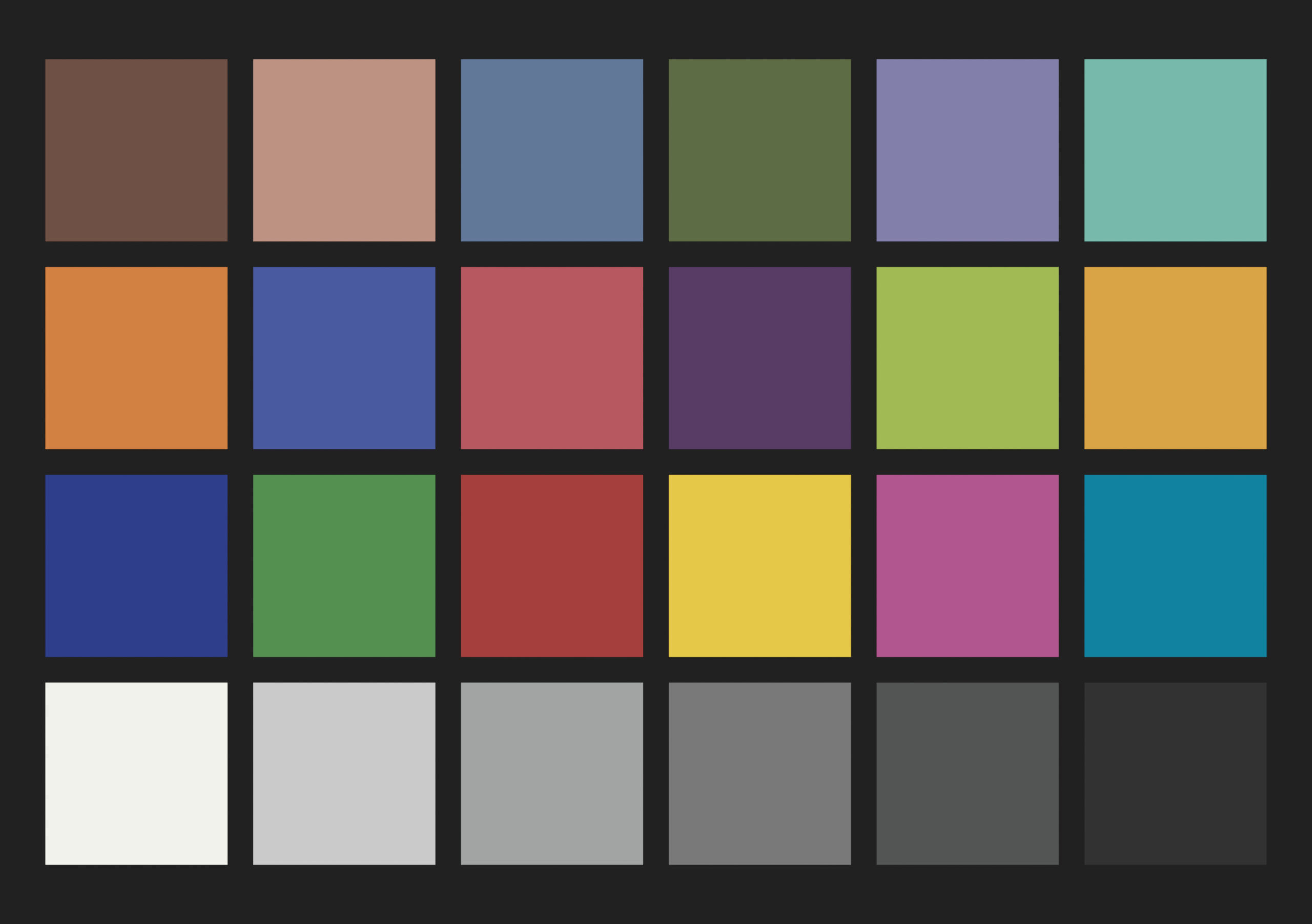
And to make the image examples as boring but simple as possible, I will only use a ColorChecker texture from the GitHub repo of “colour-science”. I am using the file “sRGB_ColorChecker2014.exr” as a texture on a camera-facing plane with only an emission shader and no lights in the Blender scene.
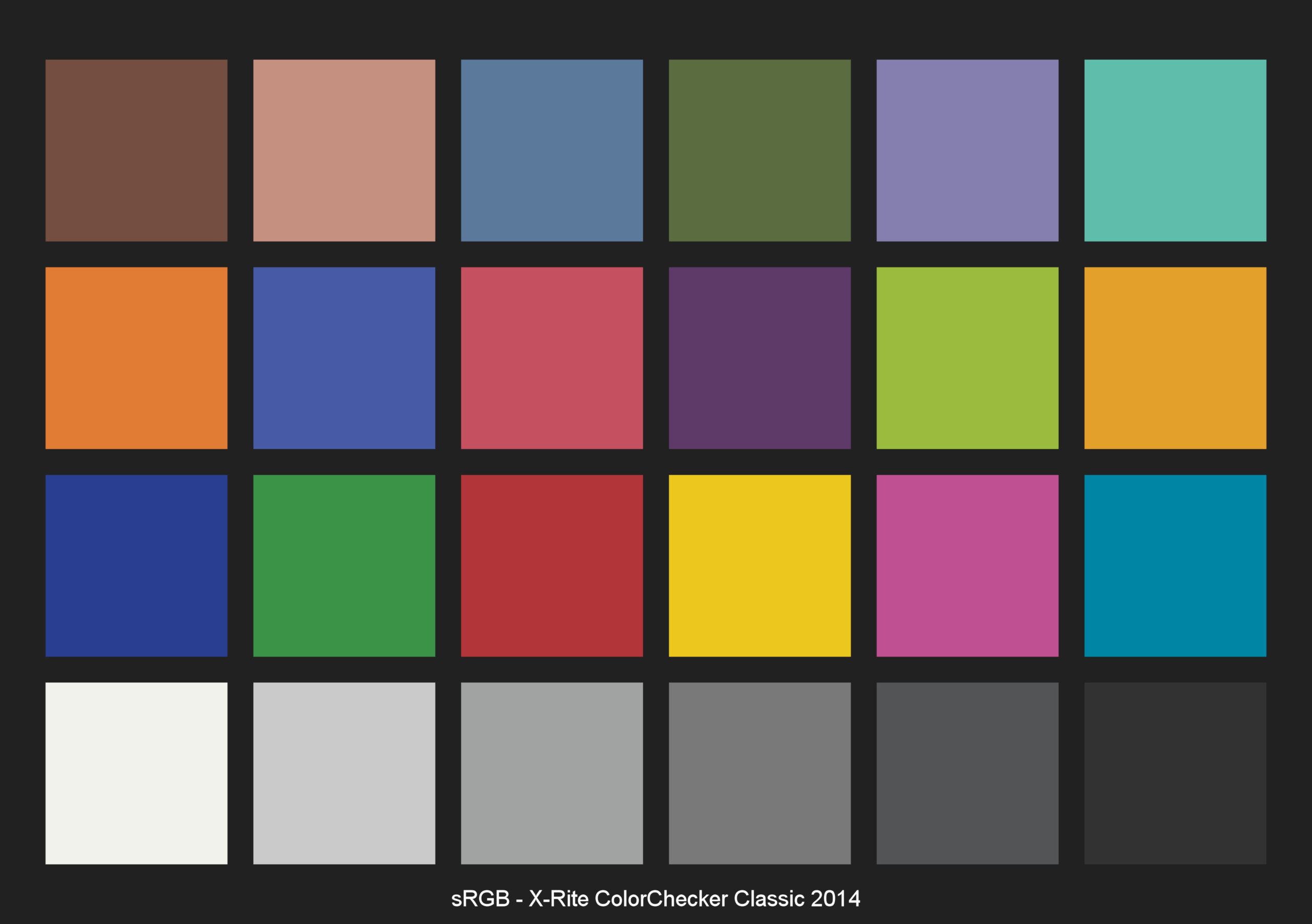

What we are seeing here are two identical images. First, a JPG image from the texture, and then a JPG image from the rendering from Blender.
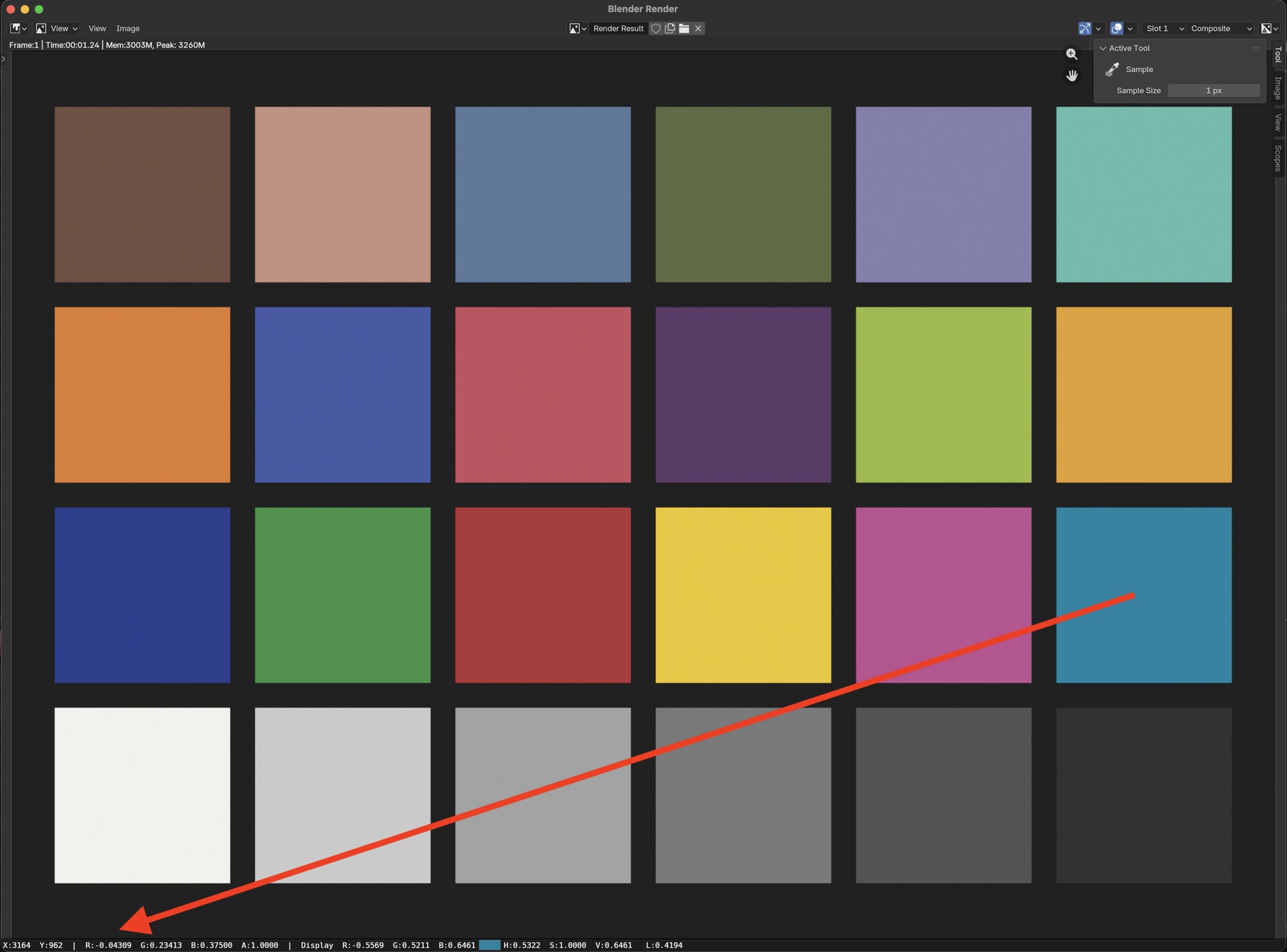
But a sample of the cyan patch in the render window of Blender shows that the red component of the cyan patch has a negative value in the red channel (-0.04309). It’s actually the only patch that has a negative RGB value.
The image processing pipeline runs as follows:
The EXR Color-checker texture image containing the negative red value goes into the Emission shader; no lights in the scene can affect the render output, so basically, the EXR texture “lands” in the render buffer of Blender still containing the negative red value in the cyan patch.
Only when choosing a direct viewing image format, such as JPG, PNG, TIFF, etc., does the inverse EOTF for sRGB display apply a clamp function and cut off every value below zero and above one.
What does the negative red value in the cyan patch mean in the working color space “Linear Rec.709”? It is out of the gamut of the primaries of Rec.709!
But I am seeing the cyan patch in the JPG images above. How can I see something that cannot be displayed on a standard sRGB display?
Maybe plotting the image data with “Colour for Python” can help to understand what is happening.
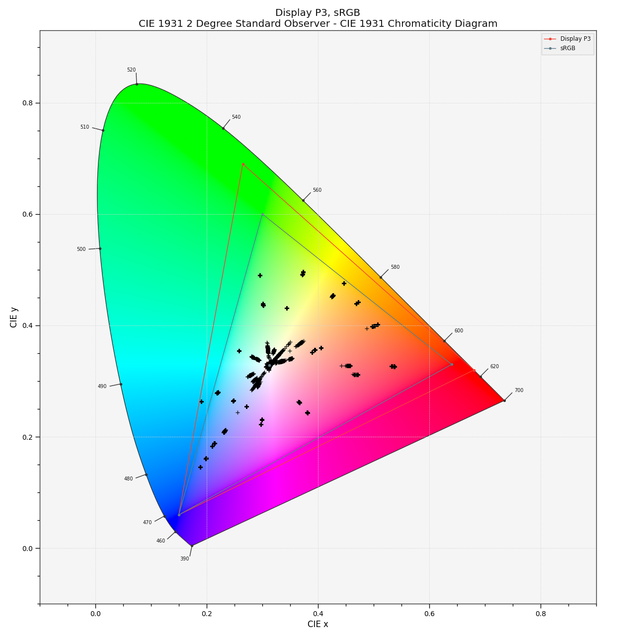
The left plot shows the image data in the working color-space, the right plot shows the image data that is sent to the display and finally visible on the screen.
The reason for several plot points per patch is the fact that the rendering has antialiased edges, which results in different RGB values than the patch itself.


The rendered file has RGB values in the cyan patch that are out of gamut in the working color space. They cannot be displayed; the plot points are outside of the triangle shown in the plot.
The simple clamp operation of the inverse EOTF of the selected display device “shifts” the RGB values slightly to the edge of the gamut. Now all the values can be displayed on an sRGB display.
So, how does the cyan patch actually look? Luckily, I am working on a Mac Studio with a Studio Display from Apple that supports the display color-space “Display P3”. And if you read this article on an Apple Notebook, an iPad, or an iPhone, you should be able to see in the next two images of a Color-checker that the cyan patch on the left is slightly different than the one on the right. The cyan patch in the left image looks more saturated.
Blender 5.x makes it also very easy now to generate a “Display P3” image. Just change the display device to “Display P3” and render a JPG, PNG, or TIFF out of Blender. The file gets a new tag called “sP3,” and this is the tag that is used on the left Color-checker image above.
In the display color-space “Display P3”, the cyan patch is inside the gamut and does not have to be altered or clipped, because it does not have a negative RGB value anymore. Although my working color space is still “Linear-Rec.709“, the proper view transform shows the correct result. The plot below shows that the cyan patch is indeed inside the gamut of “Display P3”.

One might ask, what’s the point of this exercise?
The RGB numbers that we enter through texture files, light, and shader values into the render engine have a different meaning depending on the working color space.
And when the display color-space is smaller than the working color-space, or in this case, featuring negative RGB values in the rendering, we see a different color on the display than intended.
In Blender 5.x, we can change the working color-space to Linear-Rec.2020 and ACEScg, but without a more complex display transform than an inverse EOTF, a DRT, or another picture formation process, a lot more image data will be shifted, twisted, altered, or clipped on the way out to the display.
So working in a huge working color-space does not improve the rendering per se, because the RGB values close to the edge of the gamut of Rec.2020 or ACEScg have to be color managed somehow to “arrive” properly on the destination display device, especially when the display has the smallest sRGB/Rec.709 primaries.
The fact that every RGB value between zero and one in the Linear-Rec.709 working color space has a meaning on the sRGB display can also be seen as an advantage. If the inverse EOTF, which is applied to the signal to the monitor, and the EOTF in the display cancel each other out 100%, it means that the RGB values directly drive the display emission. An RGB value of 0.2 / 0.3 / 0.5 means a red, green, and blue light emission at the display of 20, 30, and 50%. But this is a rather special case. Often, the inverse EOTF and the EOTF do not cancel each other out completely.
This concludes the first article on the topic Blender 5.x and the meaning of RGB values. I hope I can write the next one soon…
One interesting note about the plots. The plot points describe the chromaticities of each patch, the ratio between the red, green, and blue components in the image data. So even after changing the emission shader from 1.0 to 0.25 and each patch emits only a quarter of the original RGB values, the plots look identical. The luminance of the image is discarded, and only the chromaticities are plotted.